Method and System for On-Line Data-Pattern Compensated Adaptive Equalizer Control

Inactive Publication Date: 2009-04-02
FUJITSU LTD
View PDF4 Cites 8 Cited by
  • Summary
  • Abstract
  • Description
  • Claims
  • Application Information

AI Technical Summary

Benefits of technology

[0005]The present invention provides a method and a system for providing continuous adaptive control using online data-pattern compensation tha

Problems solved by technology

As with all such processing operations, of critical importa

Method used


Image

  • Method and System for On-Line Data-Pattern Compensated Adaptive Equalizer Control
  • Method and System for On-Line Data-Pattern Compensated Adaptive Equalizer Control
  • Method and System for On-Line Data-Pattern Compensated Adaptive Equalizer Control

Examples


Embodiment Construction

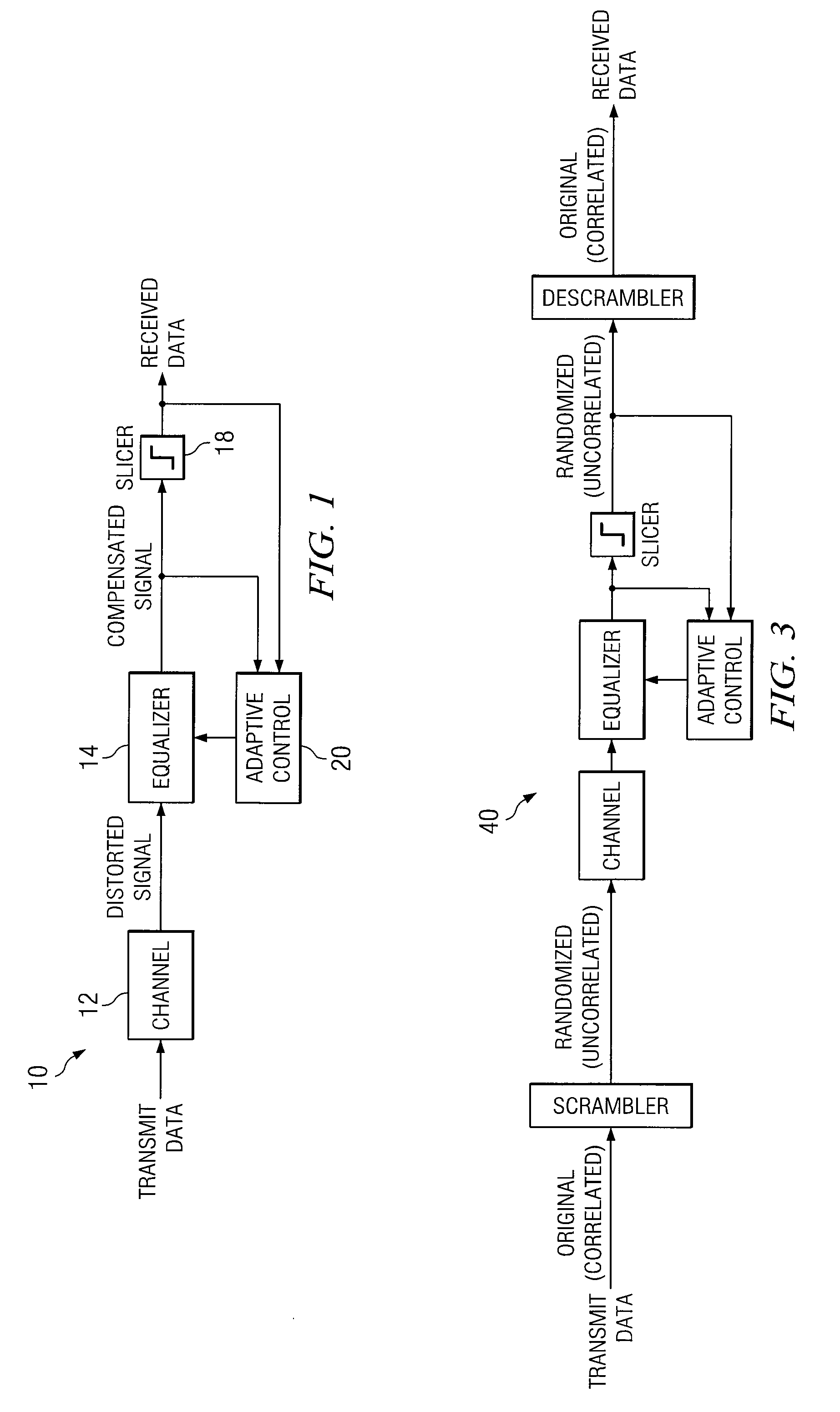
[0018]FIG. 1 is a simplified diagram illustrating a digital transmission system with an adaptive equalizer 10 related to one embodiment of the present invention. FIG. 1 includes a channel 12, an equalizer 14, a slicer 18, and an adaptive control 20.

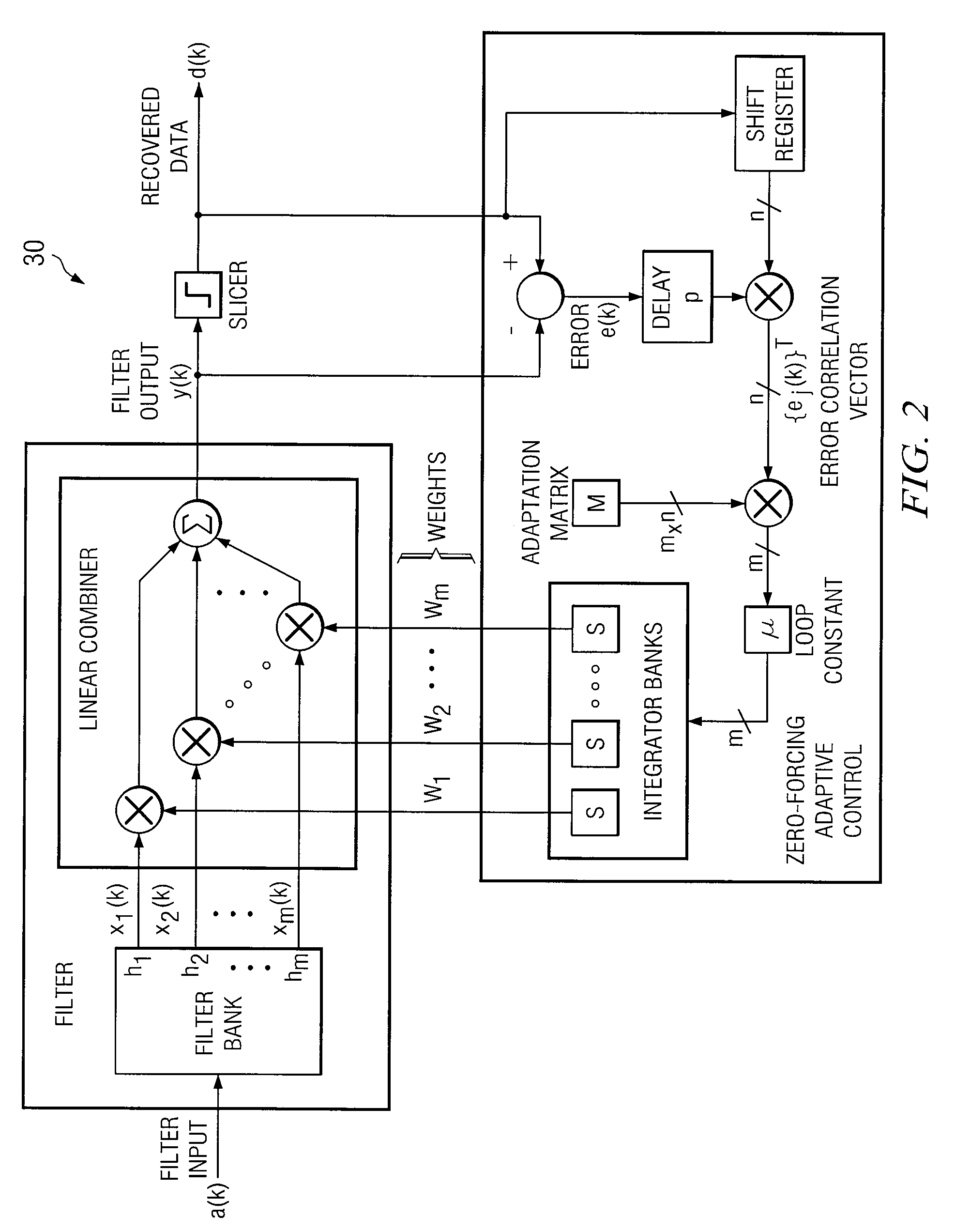
[0019]A prior scheme of the adaptive equalizer control is the general Zero-Forcing (ZF) algorithm. Filter output y(k) is a linear weighted sum of tap outputs of the filter bank. Differences between the recovered data d(k) and the filter output y(k) yields an error signal e(k). Correlation between the error signal e(k) and the recovered data d(k) [with some delays] forms error correlation vector {ej(k)}T. The error correlation vector is multiplied with an adaptation matrix M and a loop constant μ, then it is integrated to generate the tap weights {wi}T.

[0020]FIG. 2 is a simplified block diagram illustrating an adaptive equalizer 30 using the Zero-Forcing algorithm.

[0021]The general ZF algorithm can be defined, as follows:

y(k)=∑i=1mwi·xi(k)...


PUM


Abstract

In accordance with a particular embodiment of the present invention, a method is offered that includes providing a filter and an adaptive control element that is operable to communicate with the filter. The method also includes measuring, over a period, a data correlation matrix and an uncompensated error correlation vector using first and second low pass filters. In addition, the method includes implementing a data-pattern compensation matrix online, whereby the data-pattern compensation matrix is obtained online dynamically from the data correlation matrix.

Description

RELATED APPLICATIONS[0001]This application is related to U.S. patent application Ser. No. ______, entitled “METHOD AND SYSTEM FOR PROVIDING FAST AND ACCURATE ADAPTIVE CONTROL METHODS,” Attorney's Docket 073338.0476, and U.S. patent application Ser. No. ______, entitled “METHOD AND SYSTEM FOR STATIC DATA-PATTERN COMPENSATED ADAPTIVE EQUALIZER CONTROL,” Attorney's Docket 073338.0478, both filed concurrently with the present application.TECHNICAL FIELD OF THE INVENTION[0002]This invention relates generally to the field of data communications and, more specifically, to a system for on-line data-pattern compensated adaptive equalizer control.BACKGROUND OF THE INVENTION[0003]An equalization (EQ) filter is a filter, usually adjustable, typically meant to compensate for the unequal frequency response of some other signal processing circuit or system. Such filters usually allow the user to adjust one or more parameters that determine the overall shape of the filter's transfer function. Equal...

Claims


Application Information

Patent Timeline
IPC IPC(8): H03K5/159
CPCH04L2025/03624H04L25/03057
Inventor HIDAKA, YASUO
Owner FUJITSU LTD
Why Eureka
Try Eureka