Three hopper charging installation for a shaft furnace

a charging installation and shaft furnace technology, applied in the direction of furnaces, charge manipulation, lighting and heating apparatus, etc., can solve the problems of difficult to achieve adequate centering of the flow of charge material onto the distribution member in the installation, occupying a lot of space, and affecting the service life of the charging installation. achieve the effect of improving the connection

Inactive Publication Date: 2009-04-02
PAUL WURTH SA
View PDF10 Cites 11 Cited by
  • Summary
  • Abstract
  • Description
  • Claims
  • Application Information

AI Technical Summary

Benefits of technology

[0005]The invention provides a three hopper charging installation with a valve housing for the sealing valves which provides an improved connection between the parallel hoppers and the distribution device.

Problems solved by technology

In some existing three hopper charging installations this is not possible because a given opened sealing valve impedes opening of a further valve.
In consequence, such three hopper charging installations in general, and their valve housings in particular, take up a lot of space.
Furthermore, adequate centering of the flow of charge material onto the distribution member is difficult to achieve in these installations.

Method used


Image

  • Three hopper charging installation for a shaft furnace
  • Three hopper charging installation for a shaft furnace
  • Three hopper charging installation for a shaft furnace

Examples


Embodiment Construction

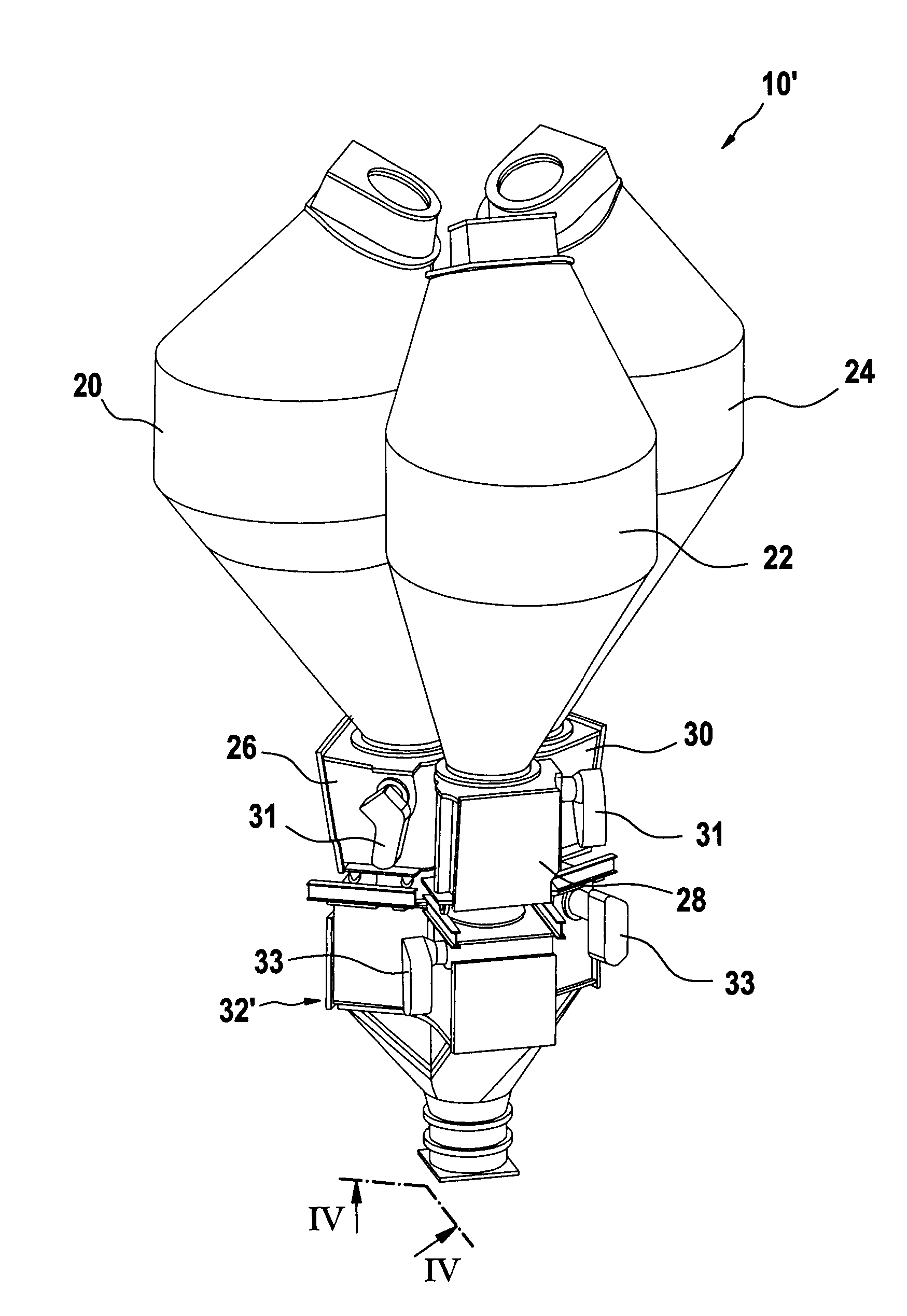
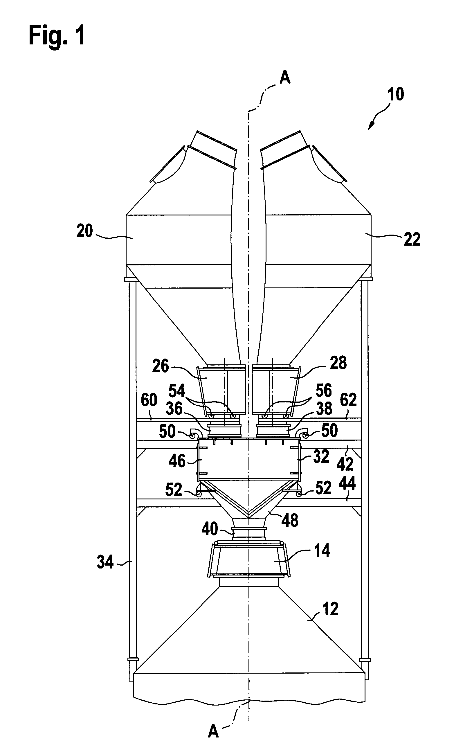
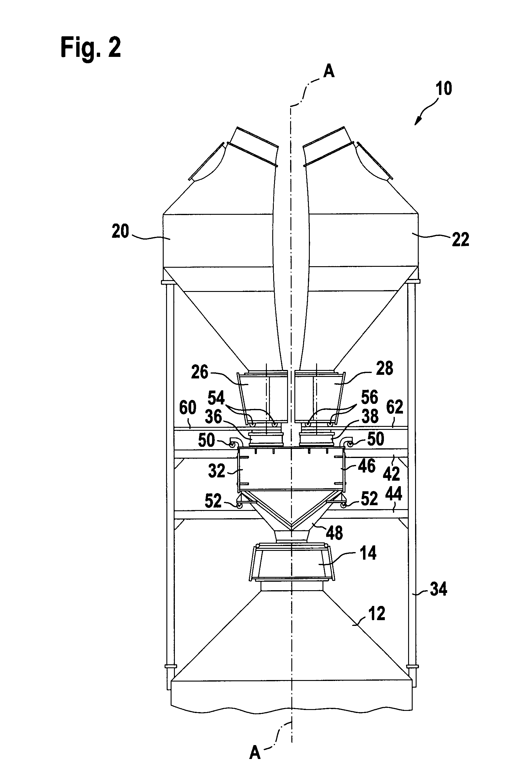
[0022]Referring to FIGS. 1-4, a two hopper charging installation, generally identified by reference numeral 10, will be described in the following first part of the detailed description.

[0023]FIG. 1 shows the two hopper charging installation 10 on top of a blast furnace 12 of which only the throat is partially shown. The charging installation 10 comprises a rotary distribution device 14 arranged as top closure of the throat of the blast furnace 12. The rotary distribution device 14 per se is of a type known from existing BELL LESS TOP installations. For distributing bulk material inside the blast furnace 12, the distribution device 14 comprises a chute (not shown) serving as distribution member. The chute is arranged inside the throat so as to be rotatable about the vertical central axis A of the blast furnace 12 and pivotable about a horizontal axis perpendicular to axis A.

[0024]As seen in FIG. 1, the charging installation 10 comprises a first hopper 20 and a second hopper 22 which...


PUM

PropertyMeasurementUnit
pivoting angleaaaaaaaaaa
slope angleaaaaaaaaaa

Abstract

A three hopper charging installation for a shaft furnace includes a rotary distribution device for distributing bulk material in the furnace by rotating a distribution member about the furnace central axis and a first, a second and a third hopper arranged in parallel above the rotary distribution device and offset from the central axis. A sealing valve housing is arranged between the hoppers and the distribution device. It has a top part with a first, a second and a third inlet respectively communicating with the first, the second and the third hopper. A first, a second and a third sealing valve are provided in the top part. Each sealing valve includes a flap which is pivotable between a closed sealing position and an open parking position. The sealing valve housing also has a funnel shaped bottom part with an outlet communicating with the distribution device. According to the invention, the top part of the sealing valve housing has a tripartite stellate configuration in horizontal section with a central portion, in which the inlets are arranged adjacently in triangular relationship about the central axis, and with a first, a second and a third extension portion, each sealing valve being adapted such that its flap opens outwardly with respect to the central axis by pivoting into a parking position located in the first, second or third extension portion respectively.

Description

TECHNICAL FIELD OF THE INVENTION [0001]The present invention generally relates to the field of charging installations for shaft furnaces such as blast furnaces. More particularly, the present invention relates to a three hopper charging installation for a shaft furnace.BRIEF DISCUSSION OF RELATED ART [0002]BELL LESS TOP charging installations have found widespread use in blast furnaces around the world. They commonly comprise a rotary distribution device equipped with a rotatable distribution member, e.g. a distribution chute which is rotatable about the vertical central axis of the furnace and pivotable about a horizontal axis perpendicular to the central axis. So called “parallel hopper top” installations comprise multiple hoppers arranged in parallel above the rotary distribution device for intermediate storage of bulk material to be fed to the distribution device. These installations allow quasi-continuous charging of bulk material, since one hopper can be (re)filled whilst anot...

Claims


Application Information

Patent Timeline
Patent Type & Authority Applications(United States)
IPC IPC(8): B65G3/00F23K3/16
CPCB65D88/32C21B7/20F27B1/20F27D3/10F27D3/0032F27D3/0033F27D3/0025
Inventor LONARDI, EMILETHILLEN, GUYGIDT, JEANHUTMACHER, PATRICK
Owner PAUL WURTH SA
Why Eureka
Try Eureka