
Color toner for flash fusing, method for producing the same, and electrostatic image developer, process cartridge, and image forming apparatus using the same

Active Publication Date: 2009-04-02
FUJIFILM BUSINESS INNOVATION CORP
View PDF15 Cites 43 Cited by
  • Summary
  • Abstract
  • Description
  • Claims
  • Application Information

AI Technical Summary

Benefits of technology

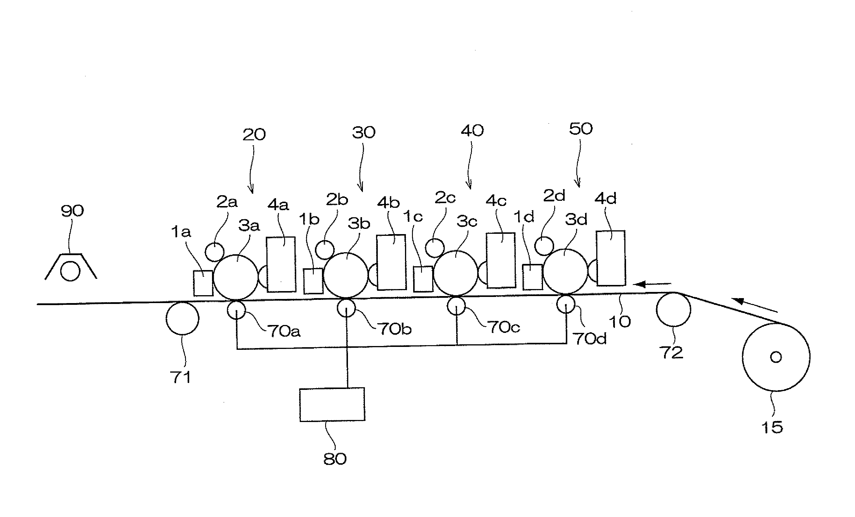
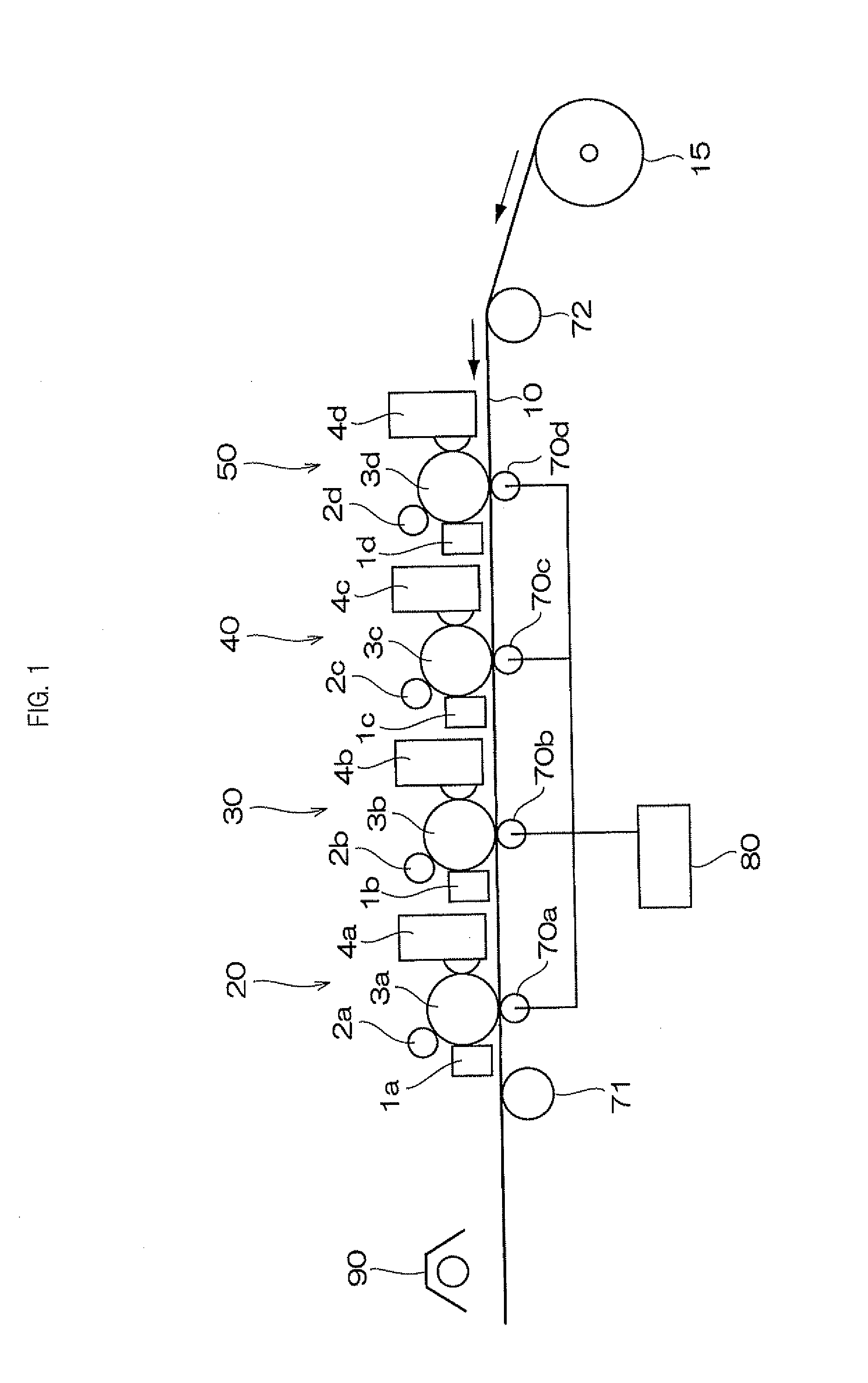
[0010]The invention provides a color toner for flash fusing, which improves fusibility of toner images in flash fusing and simultaneously reduces a fluctuation in the tone of the toner image after the fusing, a method for manufacturing the same, an electrostatic image developer, a process cartridge, and an image forming apparatus.

Problems solved by technology

However, when color toners are used for fixing, the flash fusing process is rather lower in fixing efficiency than when a black toner is used, because of the lower light absorption efficiency of the color toners.

Method used


Image

  • Color toner for flash fusing, method for producing the same, and electrostatic image developer, process cartridge, and image forming apparatus using the same
  • Color toner for flash fusing, method for producing the same, and electrostatic image developer, process cartridge, and image forming apparatus using the same
  • Color toner for flash fusing, method for producing the same, and electrostatic image developer, process cartridge, and image forming apparatus using the same

Examples


examples

[0161]Hereinafter, the present invention will be described more specifically with reference to Examples, while the invention is not limited thereby.

Preparation of Toners

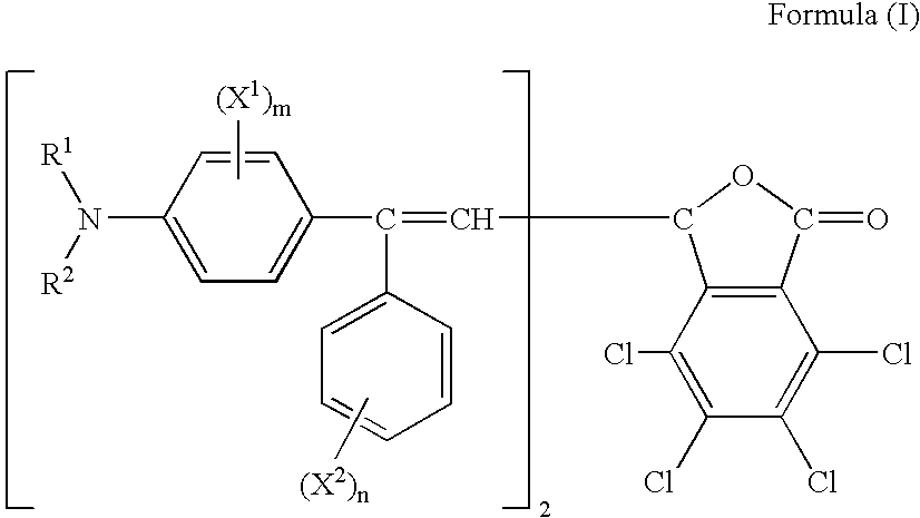
[0162]The compounds represented by Formula (I) are used as the leuco dyes in the following examples. The specific partial structures such as substituents and the λmax value of the compounds are shown in the following Table 1. In the columns for X1 or X2 in Table 1, “-” means that the m or n in Formula (I) is zero, “o-” and “p-” respectively mean that the m or n in Formula (I) is one, and “m, p” means that the m or n in Formula (I) is two. The λmax value is the wave length at an absorption peak of each of the compounds which is forming color due to activated clay and is placed in methanol-stannic chloride.

TABLE 1Com-poundNo.R1R2X1X2λmax1CH3CH3—p-OCH38902CH3CH3—p-CH39003CH3CH3—m.p (CH3)29004C2H5C2H5—p-OCH38905C2H5C2H5o-p-OCH3820OC3H76C2H5C5H11—p-OCH38907CH3—p-OCH39008C2H5—p-CH3910

[0163]Preparation of Color Forming Phas...

example 24

[0194]A toner for Example 24 is prepared by melt kneading and milling in the same manner as in Example 2 except that a toner material thereof which has the same composition as in the toner (CT-4) used in Example 3, is introduced all at once into a Henschel mixer, without the preliminary formation of a color forming phase component and decolorizing phase component.

[0195]When the toner is evaluated in the same manner as in Example 1, the absorbance ratio at 900 nm after photoirradiation is about 40%, and the fusibility in on-machine evaluation is 73%, which are inferior in fusibility to the other examples.

[0196]As shown in Tables 4 and 5, images of the Examples formed of the toners containing the fusing aid which causes decolorization by photoirradiation achieve high optical fusibility and simultaneously show excellent color reproducibility. On the other hand, the toners of the Comparative examples, which do not use the fusing aids, cause problems in any one of the on-machine properti...


PUM


Abstract

The invention provides a color toner for flash fusing containing at least: a binder resin, a colorant, a leuco dye, a developer and a decolorizer. An absorbance of the color toner after photoirradiation at a wavelength of about 900 nm is smaller than an absorbance of the color toner before the photoirradiation at the wavelength of about 900 nm. The invention further provides a method for producing the color toner, a electrostatic image developer comprising the color toner, a process cartridge comprising a developer bearing body which accommodates the electrostatic image developer, and an image forming apparatus to form a toner image by the electrostatic image developer.

Description

CROSS-REFERENCE TO RELATED APPLICATION[0001]This application claims priority under 35 USC 119 from Japanese Patent Application No. 2007-257501 filed Oct. 1, 2007.BACKGROUND[0002]1. Technical Field[0003]The present invention relates to a color toner for flash fusing processes, a process for forming the color toner, an electrostatic image developer, a process cartridge and an image forming apparatus.[0004]2. Related Art[0005]In electrophotographic processes commonly employed in copying machines, printers, printing machines, and the like, images are generally formed in the following manner: the photoconductive insulator surface of a photoreceptor drum is first uniformly charged positively or negatively (in a charging step), and then an electrostatic latent image is formed according to image information by irradiating, for example, a laser beam onto the photoconductive insulator surface and thus partially removing the electrostatic charge on the insulator surface. The latent image is th...

Claims


Application Information

Patent Timeline
IPC IPC(8): G03G9/09G03G15/01G03G9/087
CPCG03G9/0906G03G9/0912G03G15/201G03G9/0926G03G9/0928G03G9/0924
Inventor NAKAMURA, YASUSHIGE
Owner FUJIFILM BUSINESS INNOVATION CORP
Learn More