
Signal predistortion in radio transmitter

a radio transmitter and predistortion technology, applied in the field of radio transmitters, can solve the problems of power-amplified transmission signal corruption, ideally power-amplified transmission signal, and hindered information decoding at the radio receiver

Inactive Publication Date: 2009-04-02
NOKIA CORP
View PDF13 Cites 99 Cited by
  • Summary
  • Abstract
  • Description
  • Claims
  • Application Information

AI Technical Summary

Problems solved by technology

Power amplifiers are not ideal components and thus power amplification does not result in an ideally power-amplified transmission signal.
Instead, the power-amplified transmission signal is corrupted by amplitude and phase distortion caused by the power amplifier.
If this distortion is not corrected before transmission or at the radio receiver, the decoding of the information will be hindered at the radio receiver.
Additionally, the radio transmitter may produce undesired out-of-band emissions, thereby interfering other trans-ceivers operating on adjacent frequency channels.
This solution ensures that the predistortion values are always up-to-date, but the solution requires an excessive amount of signal processing, which requires high computational capacity and consumes power.

Method used


Image

  • Signal predistortion in radio transmitter
  • Signal predistortion in radio transmitter
  • Signal predistortion in radio transmitter

Examples


Embodiment Construction

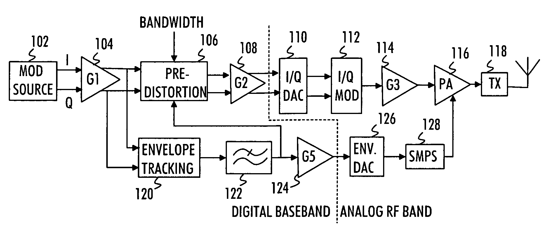
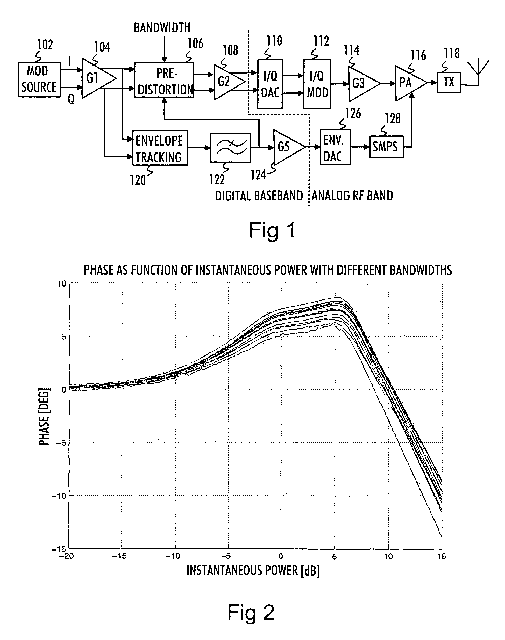
[0023]FIG. 1 is a block diagram illustrating components of a radio transmitter according to an embodiment of the invention. The radio transmitter may be a mobile communication device, for example. The block diagram of FIG. 1 illustrates components related to predistortion and power amplification of a transmission signal. All of the components illustrated in FIG. 1 are obviously not necessary for carrying out the invention.

[0024]In FIG. 1, a modulation source 102 provides a transmission signal comprising information symbols to be transmitted from the radio transmitter to a radio receiver. The transmission signal is in a digital form and divided into an in-phase (I) component and a quadrature (Q) component. The transmission signal is then fed to a first scaling circuit 104, which scales (amplifies) the transmission signal to a desired level suitable for an envelope tracking unit 120 and a predistortion unit 106. The envelope tracking unit 120 and the predistortion unit 106 may have ce...


PUM


Abstract

A transmission signal to be transmitted from a radio transmitter is predistorted in order to compensate for the signal distortion caused by a power amplifier. The predistortion parameters for at least one of envelope and phase predistortion are selected according to the bandwidth of the transmission signal. Then, the transmission signal is predistorted with the selected predistortion parameters, and the predistorted transmission signal is power-amplified in the power amplifier for transmission

Description

FIELD OF THE INVENTION[0001]The invention relates generally to radio transmitters and particularly to predistortion of a transmission signal before power amplification.BACKGROUND OF THE INVENTION[0002]In radio transmitters, a transmission signal, i.e. the signal being transmitted, is amplified in a radio frequency power amplifier which amplifies the transmission signal to a level suitable for transmission over an air interface to a radio receiver. The level of the power-amplified transmission signal should be high enough to enable the radio receiver to decode information contained in the transmission signal.[0003]Power amplifiers are not ideal components and thus power amplification does not result in an ideally power-amplified transmission signal. Instead, the power-amplified transmission signal is corrupted by amplitude and phase distortion caused by the power amplifier. If this distortion is not corrected before transmission or at the radio receiver, the decoding of the informati...

Claims


Application Information

Patent Timeline
IPC IPC(8): H04B1/00
CPCH03F1/3241H04B2001/0425H04B1/0475
Inventor NENTWIG, MARKUS
Owner NOKIA CORP
Learn More