I/Q Calibration Techniques

a calibration technique and calibration method technology, applied in the field of i/q calibration techniques, can solve problems such as signal folding onto itself, interference generated by imbalances, and mismatches in baseband circuits

Active Publication Date: 2009-04-02
MAXLINEAR INC
View PDF6 Cites 27 Cited by
  • Summary
  • Abstract
  • Description
  • Claims
  • Application Information

AI Technical Summary

Benefits of technology

[0012]A method for processing a received signal over wireless communication receiver, in accordance with another embodiment of the present invention, includes, in part, removing mismatches between in-phase and quadrature components of a first portion of a frequency spectrum of the receive signal; and removing mismatches between the in-phase and quadrature components of a second portion of the frequency

Problems solved by technology

This is important because imbalances generate interference within the received signal by folding the negative frequencies in the complex path onto the desired signal.
In a direct conversion receiver, this process causes the signal to fold onto itself, and is a well-known problem.
However, in wideband communications systems there are mismatches that occur in the baseband circuits.
Such mismatches make it difficult to achieve sideband rejection of greater than 45 dB across the band.
For example, frequency-dependent mismatches in the baseband analog signal path can result in substantial d

Method used


Image

  • I/Q Calibration Techniques
  • I/Q Calibration Techniques
  • I/Q Calibration Techniques

Examples


Embodiment Construction

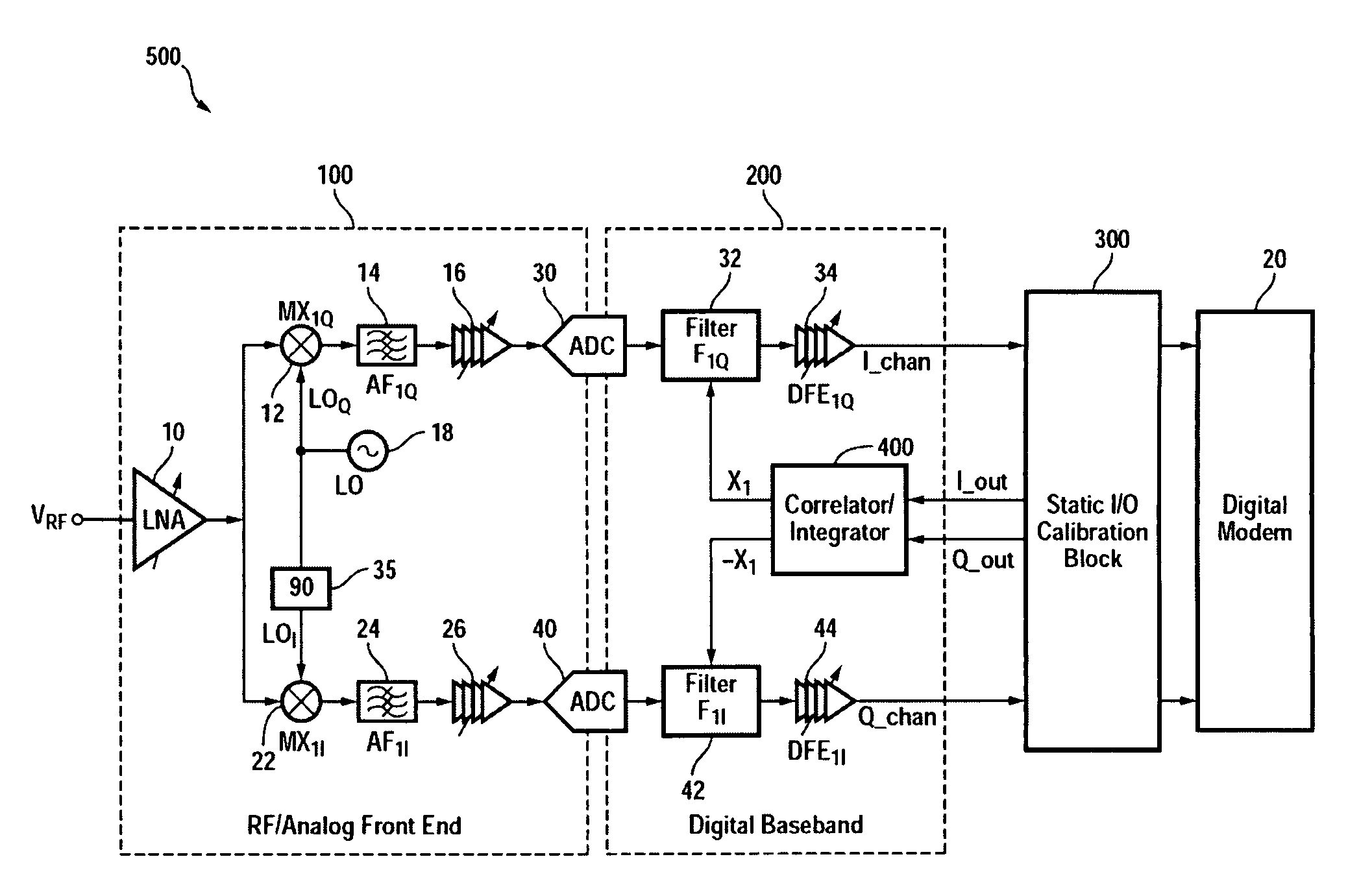
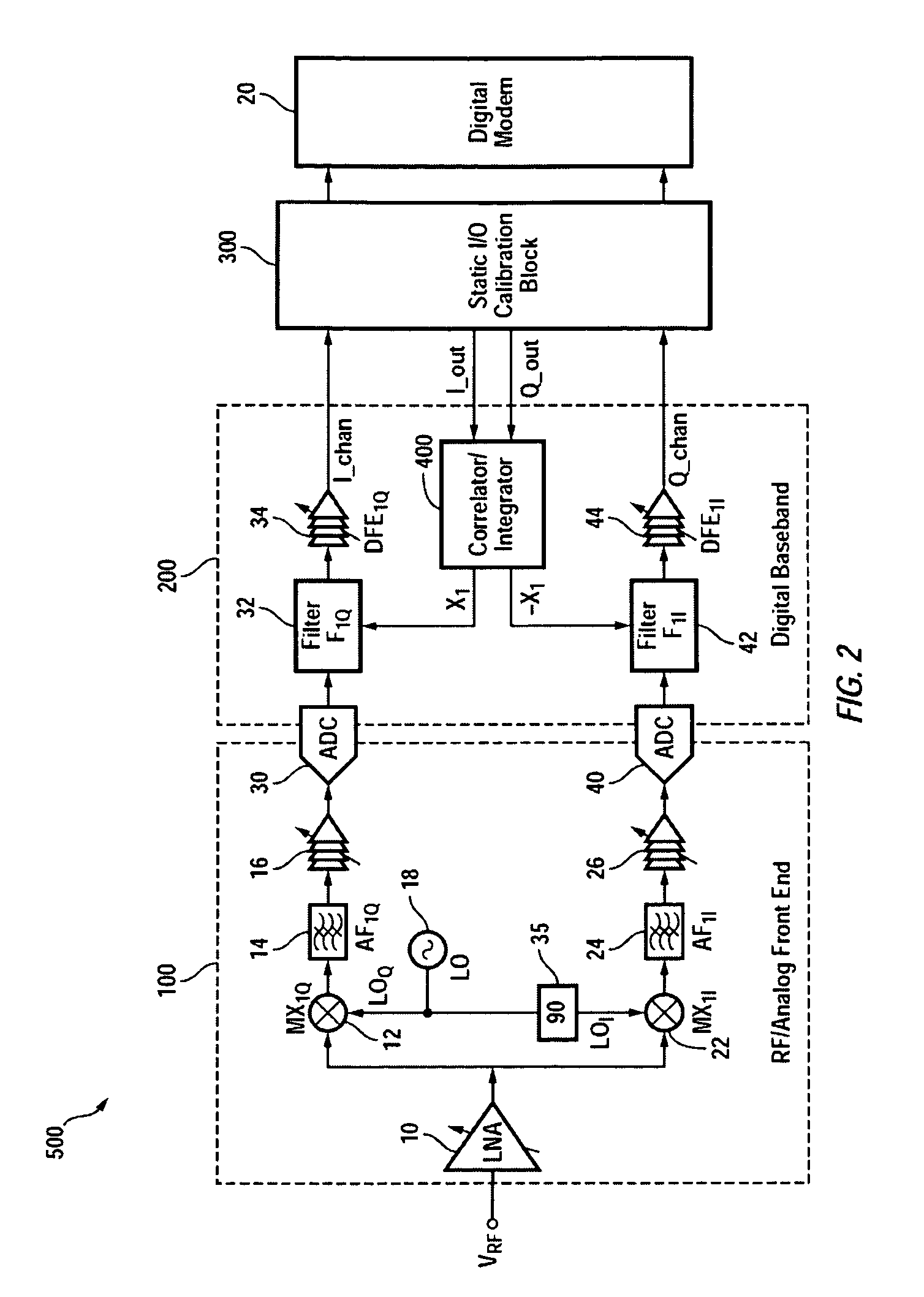
[0018]In accordance with one embodiment of the present invention, I / Q mismatches (skews) in a direct conversion receiver is substantially minimized. FIG. 2 is a block diagram of a direct conversion receiver 500 shown as including, in part, an analog front end 100, a digital baseband 200, a static I / Q calibration block 300, and a correlator / integrator 400. The baseband analog I / Q signal path mismatches, such as those from the analog filters 14 and 24, are modeled as a systematic frequency response scaling in the analog signal path transfer function. In other words, mismatches in the analog signal path are treated as being frequency dependent.

[0019]FIG. 4 is a spectrum 370 of a signal received by receiver 500. Spectrum 370 is shown as having a first portion 355 associated with I / Q mismatches that are relatively frequency-independent, and second portions 350, 352 associated with I / Q mismatches that are frequency-dependent. Portions 350 and 352 are closer to edges of the bandpass filter...


PUM


Abstract

A receiver includes a static I/Q calibration block and a correlation/integration block. The static I/Q calibration block is configured to substantially eliminate mismatches between in-phase and quadrature components of a portion of the spectrum having associated I/Q mismatches that are relatively frequency-independent. The correlation/integration block is configured to substantially eliminate mismatches between the in-phase and quadrature components of portions of the spectrum having associated I/Q mismatches that are relatively frequency-dependent in accordance with a pair of signals generated by the static I/C calibration block.

Description

CROSS-REFERENCES TO RELATED APPLICATIONS[0001]The present application claims benefit under 35 USC 119(e) of U.S. provisional application No. 60 / 976,695, filed Oct. 1, 2007, and U.S. provisional application No. 60 / 977,020, filed Oct. 2, 2007, both entitled “I / Q Calibration Techniques”, the contents of which are incorporated herein by reference in their entirety.BACKGROUND OF THE INVENTION[0002]In systems with analog or RF complex signal paths, such as direct conversion and low-IF receiver systems, it is necessary to calibrate the system's balance of in-phase (I) and quadrature (Q) amplitude and phase signals. This is important because imbalances generate interference within the received signal by folding the negative frequencies in the complex path onto the desired signal. In a direct conversion receiver, this process causes the signal to fold onto itself, and is a well-known problem. The extent to which the interference from folding is rejected is referred to as sideband rejection.[...

Claims


Application Information

Patent Timeline
IPC IPC(8): H04B1/16
CPCH04L27/0014H04B1/30
Inventor LING, CURTISYU, SHUANG
Owner MAXLINEAR INC
Why Eureka
Try Eureka