Catheter insertion device with automatic safety barrier

a technology of safety barrier and catheter insertion, which is applied in the field of medical devices for inserting an intravenous catheter into a patient, can solve the problems of increased risk of hiv transmission, increased risk of needle stick injury, and devices that require manipulation or disassembly after use, and achieve the effect of reducing the risk of infection

Active Publication Date: 2009-04-02
BECTON DICKINSON & CO
View PDF22 Cites 34 Cited by
  • Summary
  • Abstract
  • Description
  • Claims
  • Application Information

AI Technical Summary

Benefits of technology

[0018]Biasing means may bias the barrier means relative to the housing means such that withdrawing the piercing means through the opening causes the biasing means to misalign the opening with the bore. In this manner, embodiments of the p...

Problems solved by technology

Needle stick injuries may arise during planned use and exposure, and/or as a result of carelessly or maliciously discarded needles.
Of particular concern, however, are injuries from hollow-bore needles, especially those used for blood collection or intravenous (“IV”) catheter insertion.
These devices are likely to contain residual blood and are associated with an increased risk for HIV transmission.
Additionally, devices that require manipu...

Method used


Image

  • Catheter insertion device with automatic safety barrier
  • Catheter insertion device with automatic safety barrier
  • Catheter insertion device with automatic safety barrier

Examples


Embodiment Construction

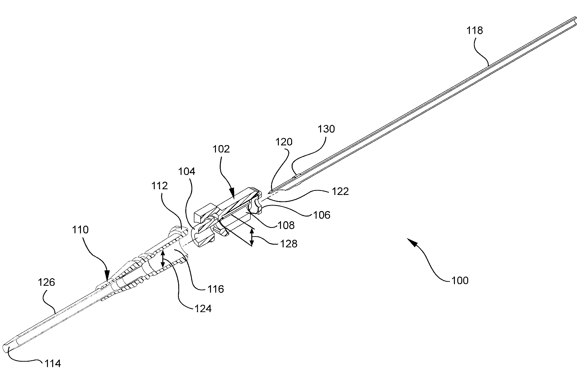
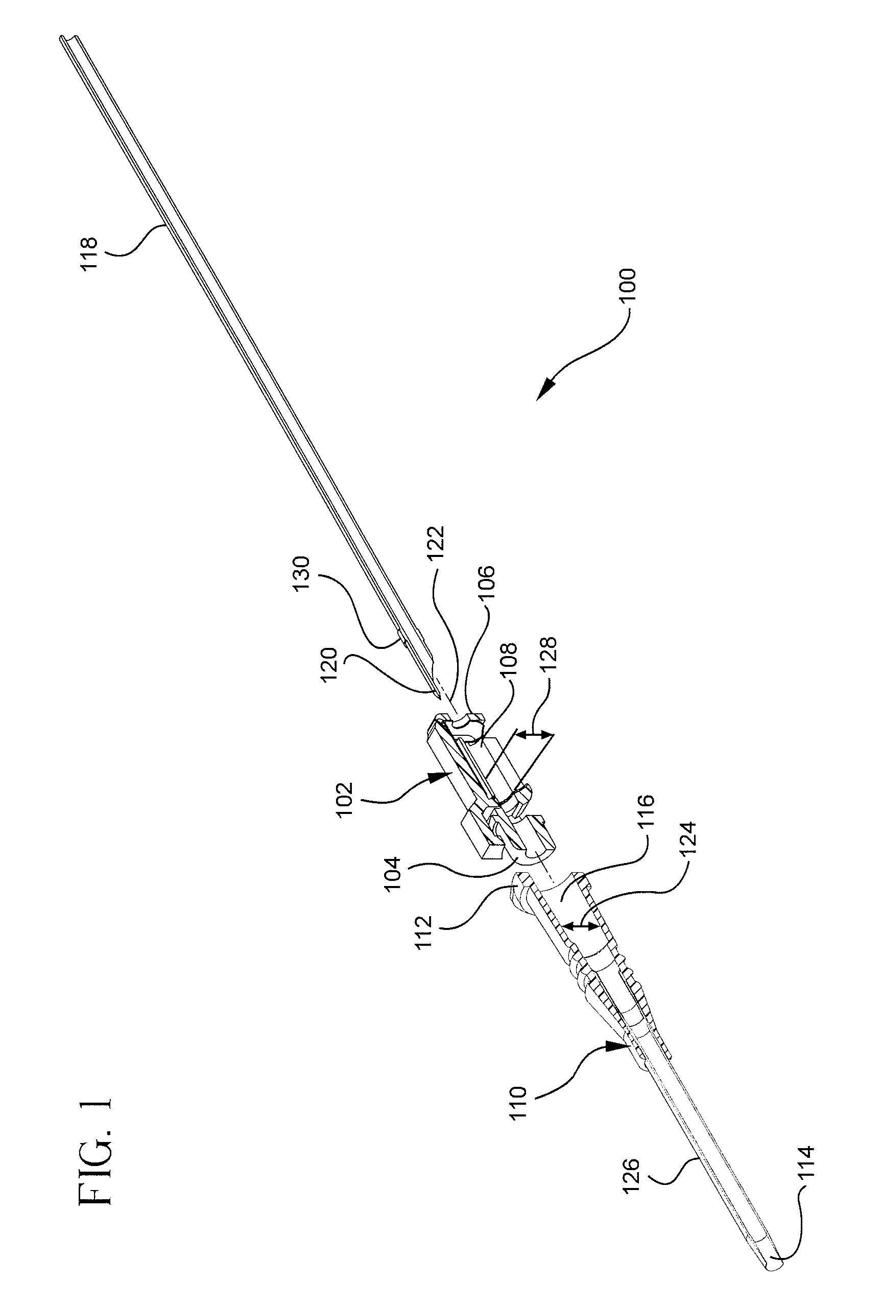
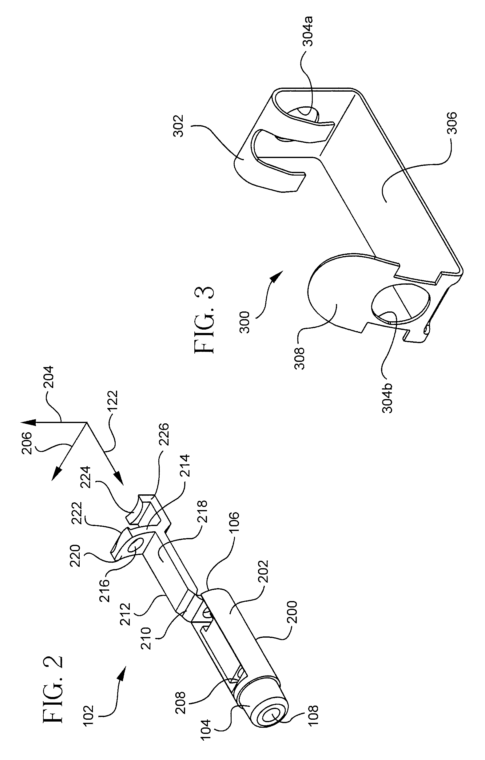
[0031]The illustrated embodiments of the present invention will be best understood by reference to the drawings, wherein like parts are designated by like numerals throughout. It will be readily understood that the components of the present invention, as generally described and illustrated in the Figures herein, may be arranged and designed in a wide variety of different configurations. Thus, the following more detailed description, as presented in the Figures, is not intended to limit the scope of the invention as claimed, but is merely representative of selected embodiments of the invention. The following description is intended only by way of example, and simply illustrates certain selected embodiments of devices, systems, and processes that are consistent with the invention as claimed herein.

[0032]As used in this specification, the term “needle” refers to any of various devices that may be used to pierce the skin to acquire intravenous access, such as a hypodermic needle, a holl...


PUM


Abstract

A catheter insertion device with an automatic safety barrier includes a housing, a barrier member, and a biasing element. The housing includes a central bore configured to receive a needle therethrough, and further includes a channel extending through the housing and intersecting the central bore. The barrier member is hingedly coupled to the housing, and includes a leg to extend through the channel. An opening in the leg substantially aligns with the central bore to accommodate the needle therethrough. The biasing element biases the barrier member relative to the housing such that withdrawing the needle through the opening causes the biasing element to misalign the opening with the central bore, thereby occluding the central bore to shield an end of the needle.

Description

BACKGROUND[0001]This disclosure relates generally to medical assemblies for the administration of fluids, and more particularly to devices for inserting an intravenous catheter into a patient for fluid administration.[0002]Hypodermic needles are notorious for spreading blood-borne diseases such as Hepatitis B, Hepatitis C, and Human Immunodeficiency Virus (“HIV”), the virus that causes Autoimmune Deficiency Syndrome (“AIDS”). Health care workers are among those most at risk for contracting such diseases, as hypodermic needles are commonly used in medical fields. Needle stick injuries may arise during planned use and exposure, and / or as a result of carelessly or maliciously discarded needles.[0003]The Federal Needle Stick Safety Act was enacted into law on Nov. 6, 2000, and is aimed at reducing the risk to health care workers arising from accidental needle sticks. Among other compliance mandates, the Federal Needle Stick Safety Act requires the use of needles with engineered needle i...

Claims


Application Information

Patent Timeline
IPC IPC(8): A61M5/32
CPCA61M5/3273A61M2005/325A61M25/0618
Inventor HARDING, WESTON F.MCKINNON, AUSTIN JASON
Owner BECTON DICKINSON & CO
Why Eureka
Try Eureka