
Robust onboard diagnostic misfire detection

a technology of misfire detection and onboard engine, applied in the direction of machines/engines, electric control, instruments, etc., can solve the problems of increasing harmful engine emissions, engine will not develop full power, and engine efficiency reduction

Inactive Publication Date: 2009-04-02
CATERPILLAR INC
View PDF15 Cites 19 Cited by
  • Summary
  • Abstract
  • Description
  • Claims
  • Application Information

AI Technical Summary

Benefits of technology

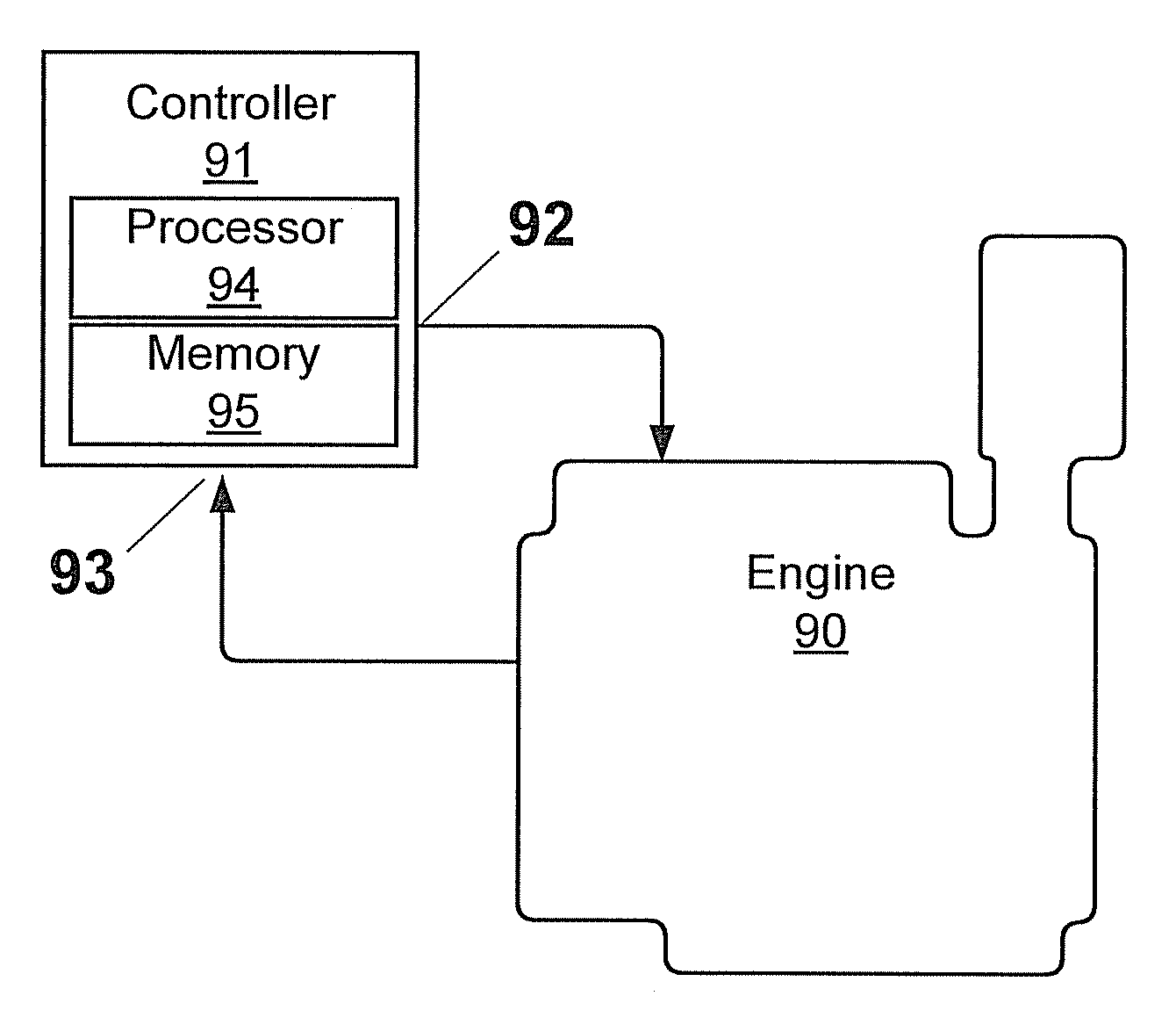
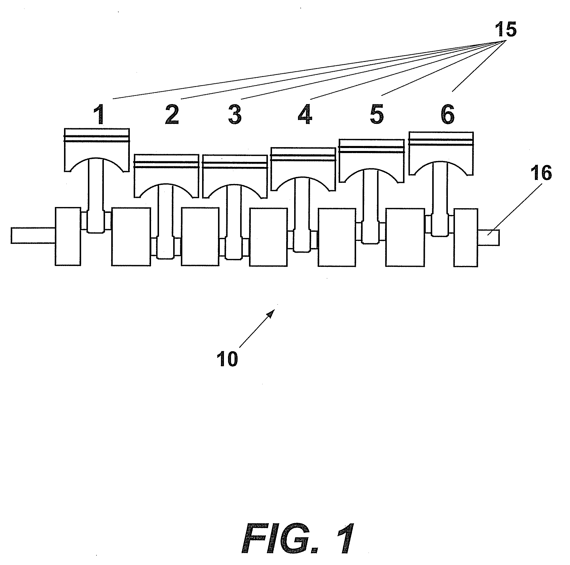
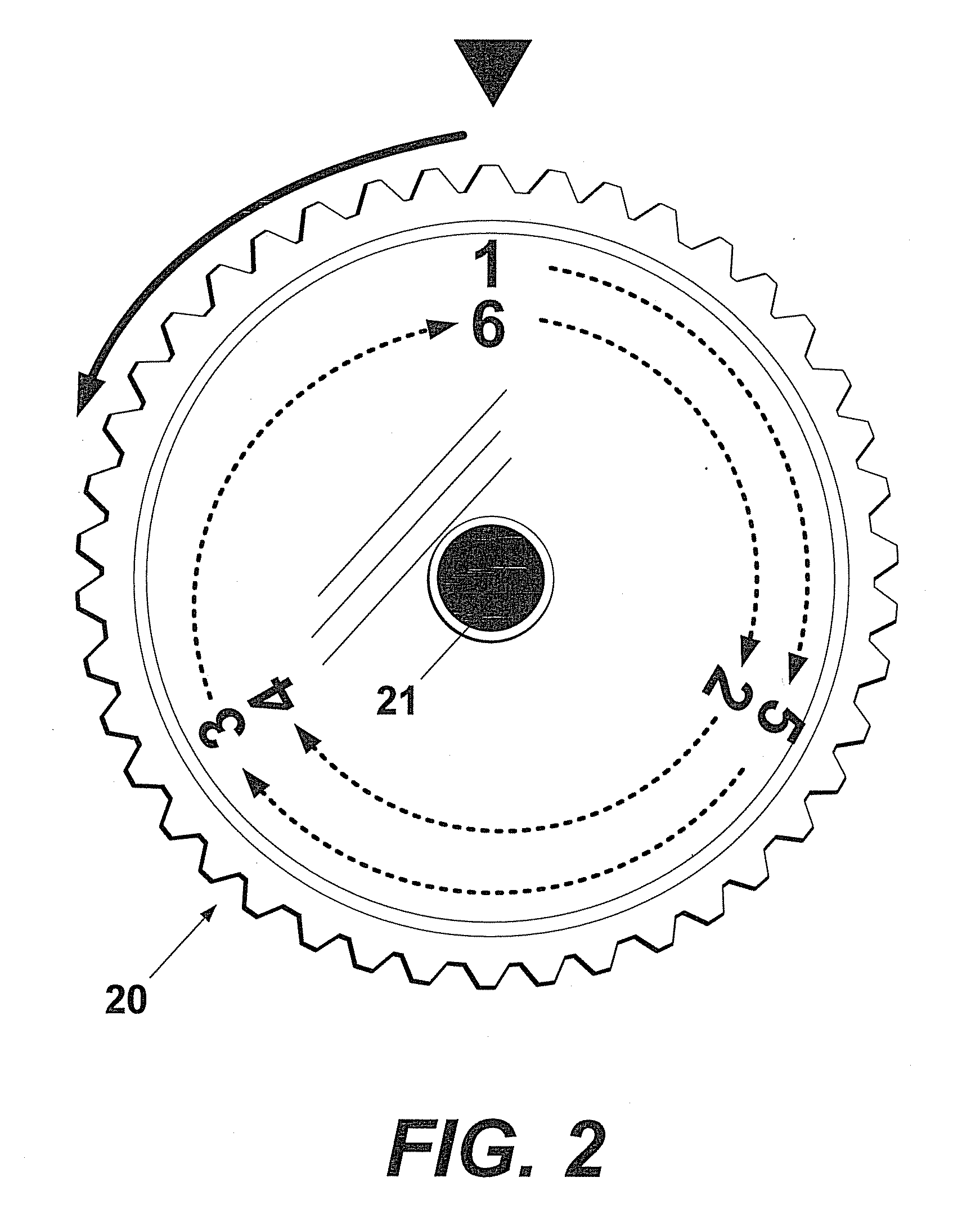
[0009]The disclosed principles pertain to a method for onboard diagnosis of engine performance for a multi-cylinder internal combustion engine. The onboard diagnosis process determines whether one or more cylinders of the engine are misfiring by detecting the engine speed as a function of the rotational angle of the crankshaft and determining crankshaft acceleration as a function of the power stroke of each cylinder. After ordering the cylinde

Problems solved by technology

However, the engine will not develop full power under such circumstances due to the absent power strokes.
In addition, the presence of continual misfires will reduce engine efficiency, increase harmful engine emissions, and may damage exhaust treatment components.
The reduction in engine efficiency is the result of nonfunctioning cylinders imposing drag on the other cylinders, as well as the ejection of raw fuel into the exhaust stream.
The thermal cycling induced by the presence of raw fuel in the exhaust may also degrade catalytic converter components, further exacerbating the emissions problems caused by the misfires.
However, it has traditionally been difficult to reliably detect misfires.
However, the present inventors have discovered that such techniques, while functioning satisfactorily to detect single-cylinder misfires, do not reliably identify misfires when multiple cylinders are misfiring.
At the same time, such systems are much more likely to signal false positives, i.e., to signal a misfire when none is present.

Method used


Image

  • Robust onboard diagnostic misfire detection
  • Robust onboard diagnostic misfire detection
  • Robust onboard diagnostic misfire detection

Examples


Embodiment Construction

[0019]This disclosure relates to an on board diagnostic system for detecting cylinder misfires in a multi-cylinder engine. As noted above, cylinder misfires cause fuel inefficiency and harmful emissions. In the case of heavy-duty industrial engines, these problems can have significant cost and regulatory impacts. Indeed, it appears that as of 2010, engines will be required by the United States Environmental Protection Agency and California Air Resources Board to have an onboard diagnostics system capable of detecting a cylinder that continually misfires (i.e., with no intervening partial or full combustion power strokes during the test period). These regulations will require that the onboard diagnostics system detect a cylinder that continuously misfires during engine idle. For purposes of those regulations, the term “idle” denotes a situation wherein the accelerator pedal or other throttle actuator is released and the machine speed and load are less than respective predefined small...


PUM


Abstract

A misfire detection system and method for onboard diagnosis of engine performance detects an engine speed as a function of a rotational angle of the crankshaft, and determines crankshaft acceleration as a function of this angle based on the detected engine speed. In this manner, the power stroke acceleration of each cylinder is determined and ranked. After excluding the greatest acceleration, the accelerations of a group of consecutively ordered cylinders including the second greatest acceleration are averaged to produce an assessment level against which the remaining lower-ranked cylinders are evaluated to detect misfires.

Description

CROSS-REFERENCE TO RELATED APPLICATIONS[0001]This patent application is a continuation-in-part of copending U.S. patent application Ser. No. 11 / 863,107, filed Sep. 27, 2007, the contents of which are hereby incorporated by reference.TECHNICAL FIELD[0002]This patent disclosure relates generally to onboard engine diagnostics and, more particularly to a robust system for determining whether a multi-cylinder engine is misfiring on one or more cylinders.BACKGROUND[0003]Internal combustion engines are typically driven by a series of combustion events timed to drive one or more pistons within cylinders. Each such combustion event in a cylinder initiates what is often referred to as a “power stroke” for that cylinder. In 4-cycle engines, there are two crankshaft revolutions (4 one-way strokes) for each power stroke. Most engines in use today for transportation and industry are of a 4-stroke design, although 2-stroke engines are still employed for smaller engines where emission regulations a...

Claims


Application Information

Patent Timeline
IPC IPC(8): G01M15/11G01M15/00F02D45/00B60Q11/00
CPCB60Q9/00F02D41/0087F02D41/08Y02T10/40F02D41/22F02D2200/1015G01M15/11F02D41/1498
Inventor LIN, GEORGEWACKERLIN, DREW
Owner CATERPILLAR INC
Learn More