Touch panel and input device using the same

Inactive Publication Date: 2009-04-09
PANASONIC CORP
View PDF3 Cites 47 Cited by
  • Summary
  • Abstract
  • Description
  • Claims
  • Application Information

AI Technical Summary

Benefits of technology

[0019]The foregoing structure allows the presence of the weak adhesion layer to remove the touch panel with ease from the cover of the apparatus when the touch panel once bonded to the cover should be peeled off and retrofitted again to the cover. At the same time, the strong adhesion layer bonded to the weak adhesion layer is peeled off toget

Problems solved by technology

In such a case, it is needed to remove bonding layer 6 left on the underside of

Method used


Image

  • Touch panel and input device using the same
  • Touch panel and input device using the same
  • Touch panel and input device using the same

Examples


Embodiment Construction

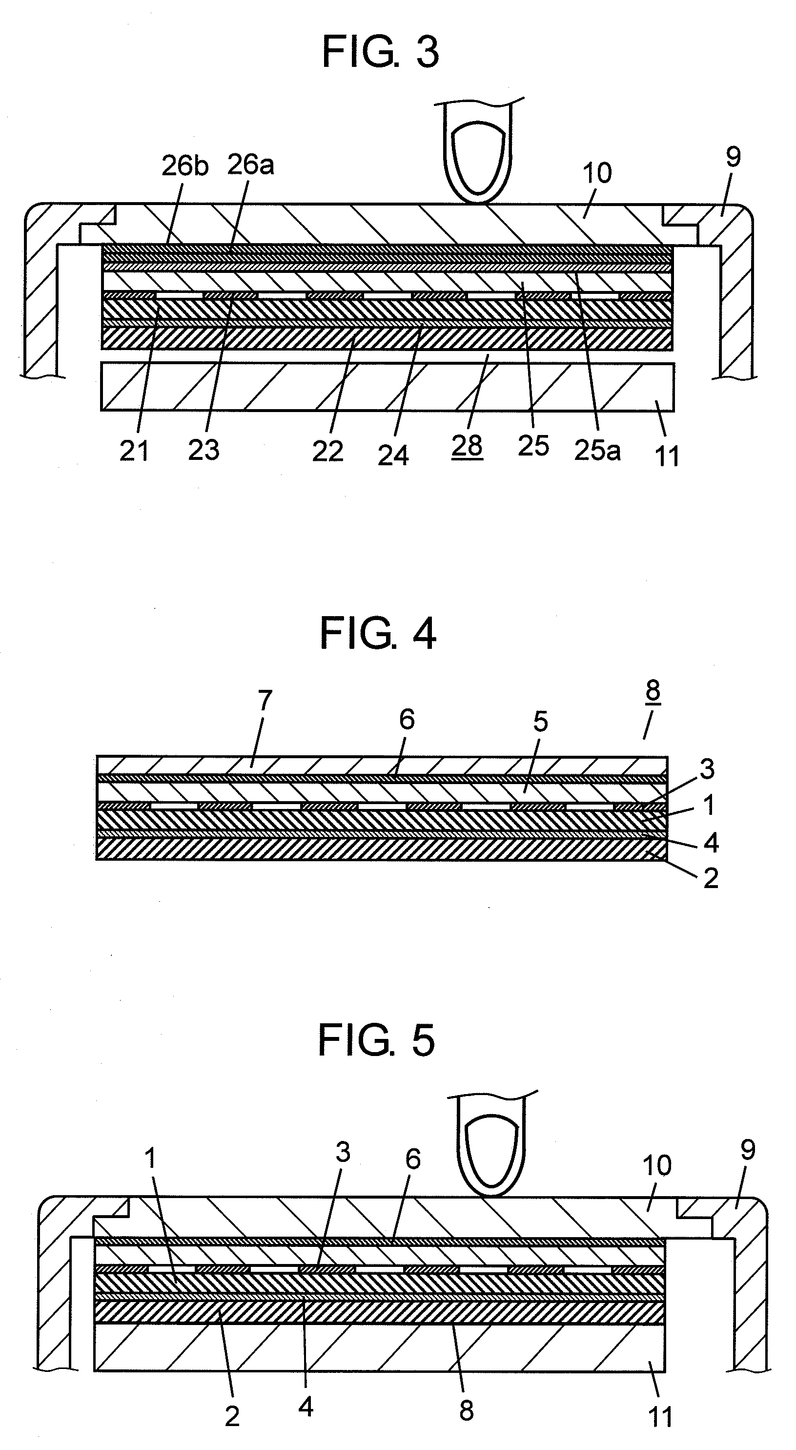
[0029]An exemplary embodiment of the present invention is demonstrated hereinafter with reference to FIG. 1-FIG. 3. For the better understanding of the structure, dimensions in the thickness direction are enlarged in the drawings. Similar elements to those in respective drawings have the same reference marks, and the descriptions thereof are sometimes omitted.

Exemplary Embodiment

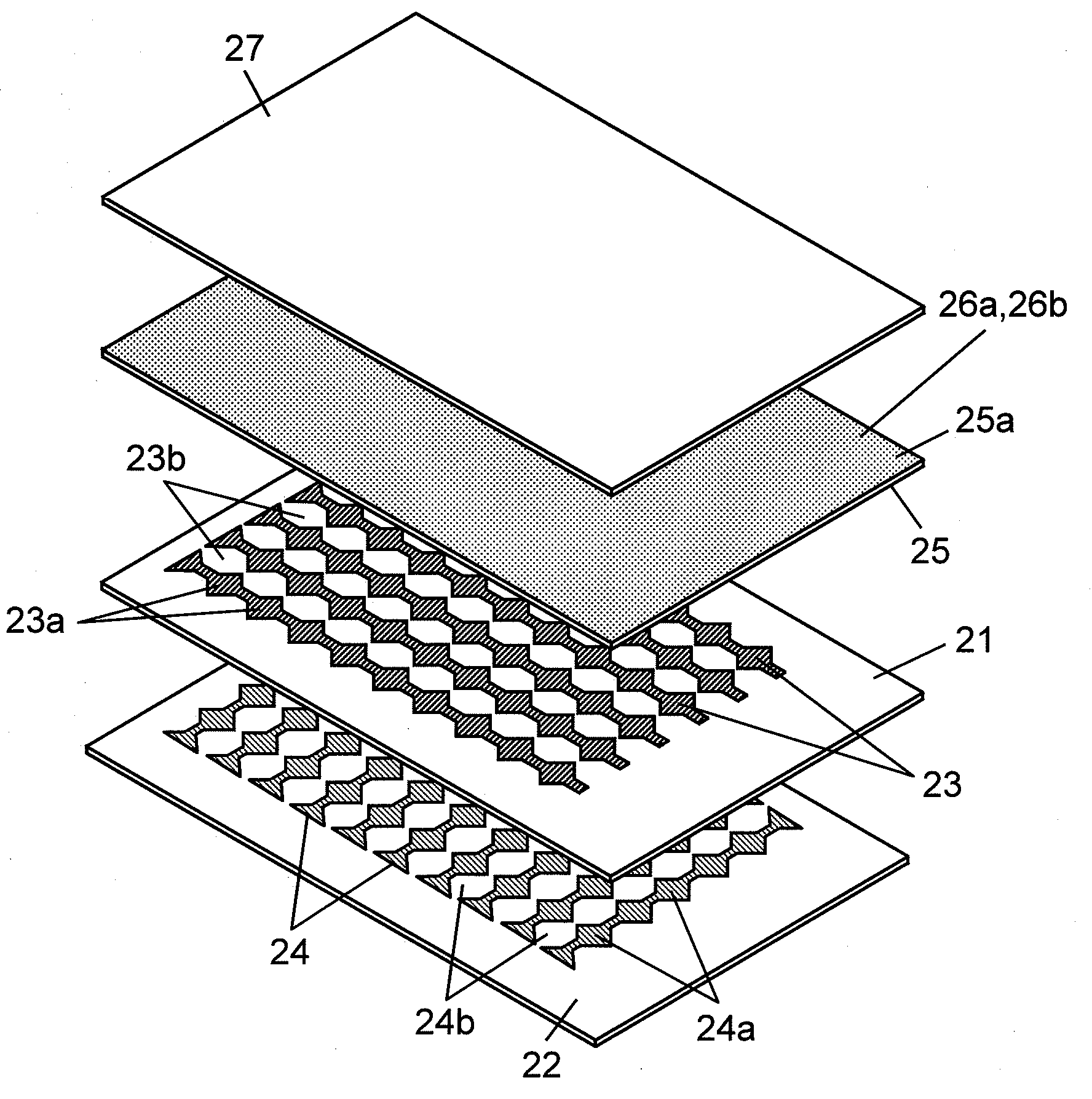
[0030]FIG. 1 shows a sectional view of a touch panel in accordance with the embodiment of the present invention. FIG. 2 shows an exploded perspective view of the touch panel. In FIG. 1 and FIG. 2, light transmissible upper substrate 21 and lower substrate 22 are made from polyether-sulfone, polycarbonate, polyethylene-terephthalate, or the like and substrates 21 and 22 are formed like film. Multiple upper conductive layers 23 shaped like a belt are formed on the top faces of upper substrates 21, and multiple lower conductive layers 24 shaped like a belt are formed on the top face of lower substrate 22. Both ...


PUM

PropertyMeasurementUnit
Timeaaaaaaaaaa
Forceaaaaaaaaaa
Adhesion strengthaaaaaaaaaa

Abstract

A touch panel includes multiple belt-like upper conductive layers and lower conductive layers formed in an orthogonal direction to the upper conductive layers. Those two kinds of layers are formed on a light transmissible substrate. A strong adhesion layer and a weak adhesion layer are layered together on a top face or an underside of the light transmissible substrate. The presence of the weak adhesion layer allows peeling off the touch panel from a cover of an apparatus fairly easier when the touch panel needs to be retrofitted to the cover. Since the weak adhesion layer is peeled off together with the strong adhesion layer, it will not be transferred or attached onto the cover. No time or labor is thus needed for removing the layer transferred or attached to the cover. The touch panel capable of being retrofitted with ease is thus obtainable.

Description

FIELD OF THE INVENTION[0001]The present invention relates to a touch panel to be used for operating a variety of electronic apparatuses, and an input device using the same touch panel.BACKGROUND OF THE INVENTION[0002]In recent years, a variety of electronic apparatuses, including cell phones and car navigation systems, have been downsized and sophisticated. This market trend has increased the use of touch panel mounted to various apparatuses for switching the functions of those apparatuses. For instance an optically transparent and electrostatic touch panel is mounted on the front of display element such as a liquid crystal display device. Through this touch panel, letters, symbols, or patterns displayed on the display element behind the touch panel can be selected with a finger or a dedicated pen, thereby switching the functions. A touch panel excellent in visible recognition and workability among others is required from the market.[0003]A conventional touch panel and an input devi...

Claims


Application Information

Patent Timeline
IPC IPC(8): G06F3/041B32B7/00
CPCY10T428/24058G06F3/044G06F3/0445
Inventor MATSUMOTO, KENICHITANABE, KOJI
Owner PANASONIC CORP
Why Eureka
Try Eureka