Value structure
a value structure and micro-pump technology, applied in the direction of piston pumps, positive displacement liquid engines, valve housings, etc., can solve the problems of inability to open, uneven pumping force of fluid, and inability to push fluid through the central valve lid, etc., to enhance the efficiency of opening and closing, and the effective flow path cross section is larg
- Summary
- Abstract
- Description
- Claims
- Application Information
AI Technical Summary
Benefits of technology
Problems solved by technology
Method used
Image
Examples
first embodiment
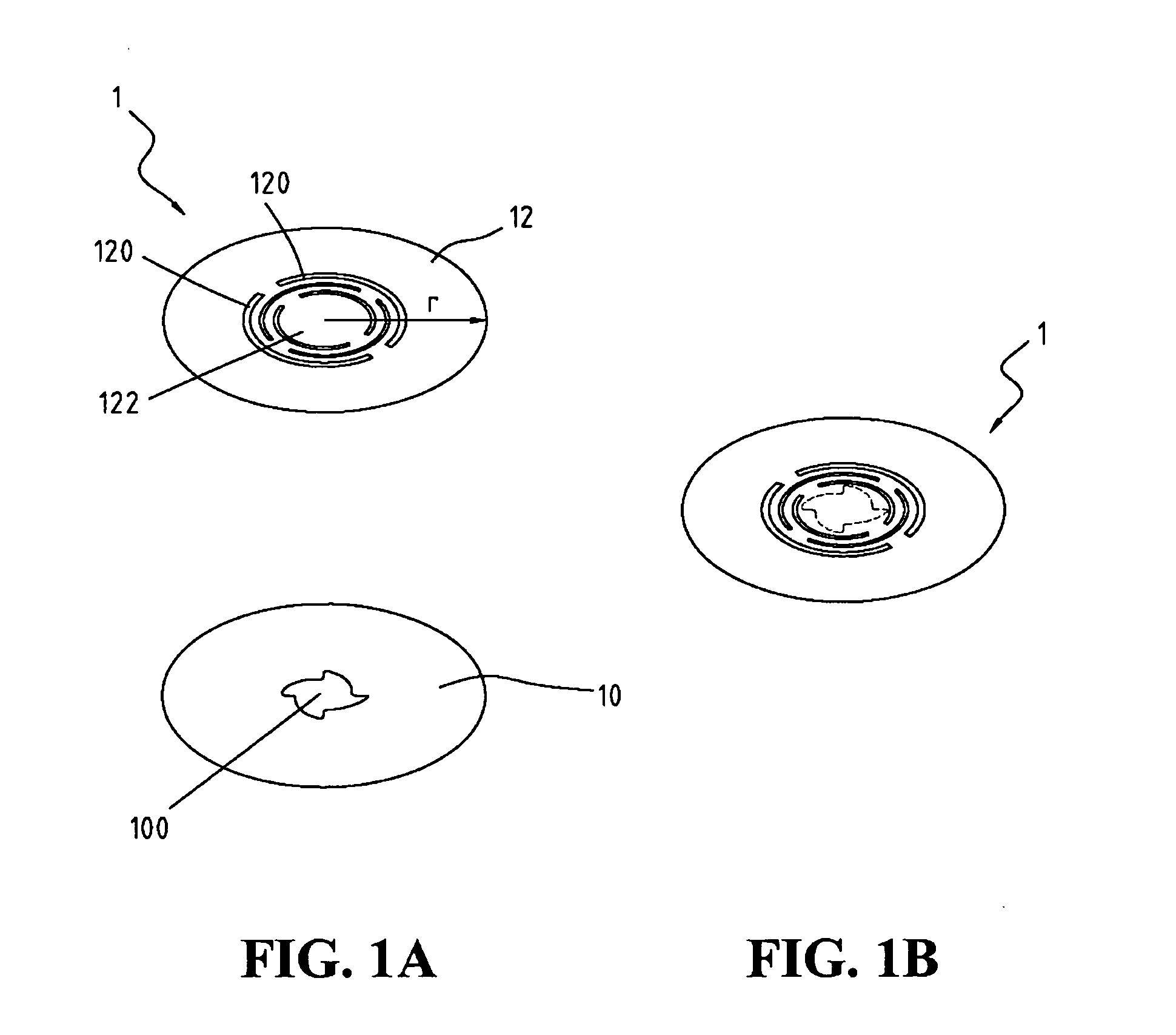
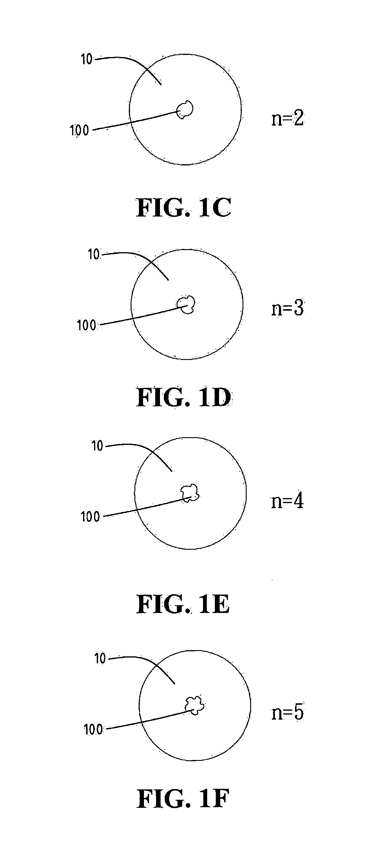
[0038]Referring to FIGS. 1A and 1B, a valve structure according to the present invention is illustrated. It can be seen in FIGS. 1A and 1B that a valve 1 of the present invention includes a valve opening diaphragm 10 and a valve diaphragm 12. The valve opening diaphragm 10 has a valve opening 100 disposed at the center thereof with a plurality of wave shaped projections. There are four wave shaped projections shown in FIG. 1A. Nevertheless, it is noted that the number of wave shaped projections surrounding the valve opening 100 of the valve opening diaphragm 10 is capable being n and n=2,3,4, . . . ,360. FIGS. 1C, 1D, 1E, 1F and 1G show two, three, four, five and six wave shaped projections respectively. Besides, the valve diaphragm 12 is stacked on the valve opening diaphragm 10 and provides at least a pair of narrow circular grooves 120 symmetrically disposed to surround the center thereof and the area 122 enclosed with the circular grooves 120 is capable of covering the valve ope...
second embodiment
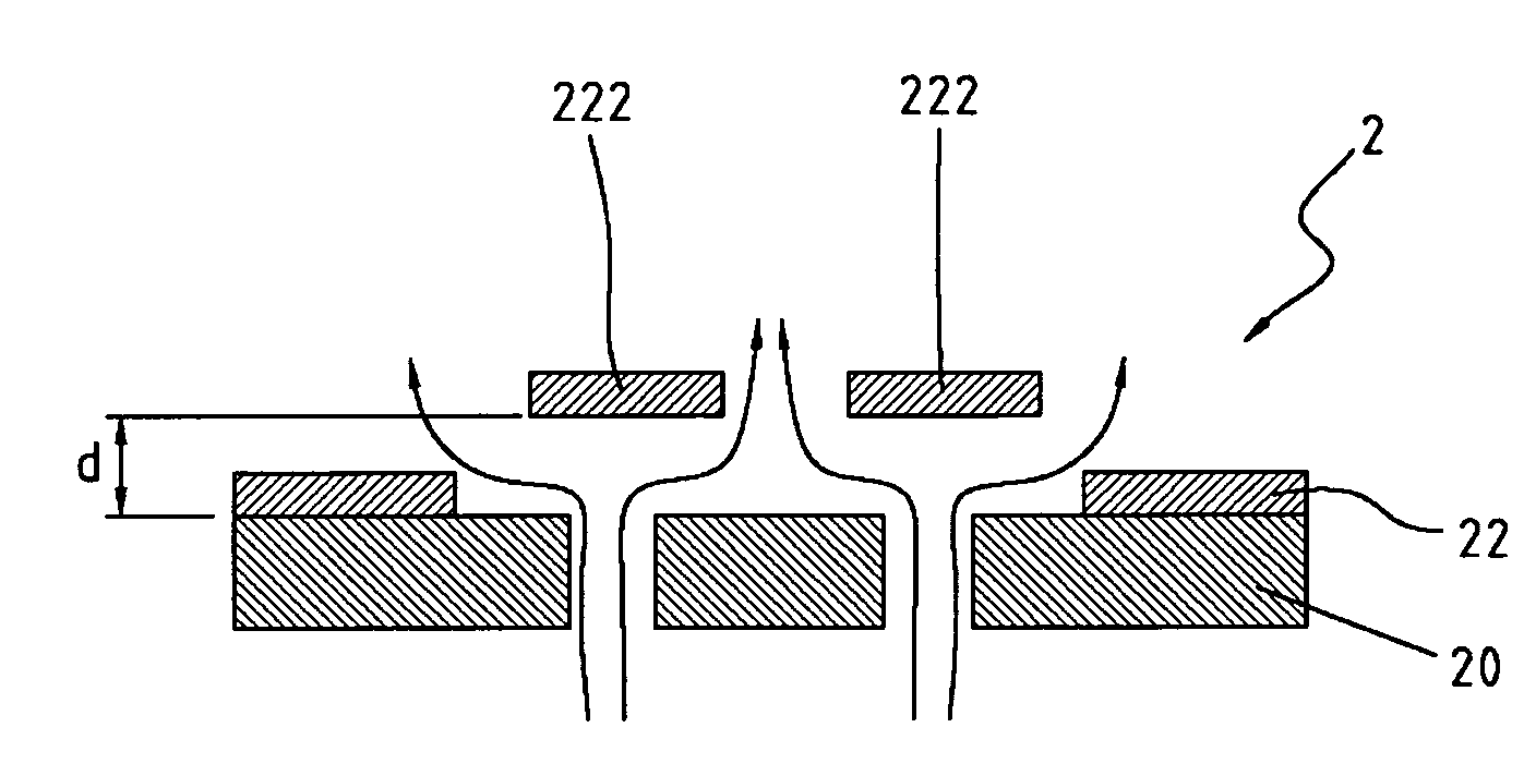
[0040]Referring to FIGS. 2A and 2B, a valve structure according to the present invention is illustrated. It can be seen in FIGS. 2A and 2B that a valve 2 of the present invention includes a valve opening diaphragm 20 and a valve diaphragm 22. The valve opening diaphragm 10 has a plurality of valve openings 200 disposed to equidistantly surround the center thereof. There are five valve openings 200 shown in FIG. 1A and the valve openings 200 can be provided with a half-moon shaped aperture respectively. Nevertheless, it is noted that the number of the valve openings 200 of the valve opening diaphragm 20 is capable being n and n=2,3,4, . . . ,20,000 based on specific design. FIGS. 2C, 2D, 2E, 2F and 2G show two, three, four, five and six valve openings 200 respectively. Besides, the valve diaphragm 12 is stacked on the valve opening diaphragm 10 and provides a central hole 221 and at least a pair of narrow circular grooves 120 symmetrically disposed to surround the center of the centr...
PUM
| Property | Measurement | Unit |
|---|---|---|
| Thickness | aaaaa | aaaaa |
| Thickness | aaaaa | aaaaa |
| Thickness | aaaaa | aaaaa |
Abstract
Description
Claims
Application Information
 - R&D
- Intellectual Property
- Life Sciences
- Materials
- Tech Scout
- Unparalleled Data Quality
- Higher Quality Content
- 60% Fewer Hallucinations
Browse by: Latest US Patents, China's latest patents, Technical Efficacy Thesaurus, Application Domain, Technology Topic, Popular Technical Reports.
© 2025 PatSnap. All rights reserved.Legal|Privacy policy|Modern Slavery Act Transparency Statement|Sitemap|About US| Contact US: help@patsnap.com


