Steel bar grating connecting structure for multi-arch underground excavation pipe gallery primary support structure and construction method

A technology for connecting structures and steel grids, which is applied in earthwork drilling, wellbore lining, tunnel lining, etc., can solve problems such as difficulties in the construction and handling of steel grids, and achieve the effects of saving construction time, improving construction progress, and reducing impacts

Inactive Publication Date: 2021-03-12
BEIJING MUNICIPAL ROAD & BRIDGE
View PDF8 Cites 0 Cited by
  • Summary
  • Abstract
  • Description
  • Claims
  • Application Information

AI Technical Summary

Problems solved by technology

[0004] The purpose of the present invention is to provide a connection plate design for the initial support structure of the underground excavation pipe gallery that facilitates the co-construction of the steel bar grid in the two adjacent warehouses, so as to solve the problem of the co-construction of the steel bar grid in the two warehouses proposed in the above-mentioned background technology. Difficult problems in the construction of the connection position

Method used


Image

  • Steel bar grating connecting structure for multi-arch underground excavation pipe gallery primary support structure and construction method
  • Steel bar grating connecting structure for multi-arch underground excavation pipe gallery primary support structure and construction method
  • Steel bar grating connecting structure for multi-arch underground excavation pipe gallery primary support structure and construction method

Examples


Embodiment

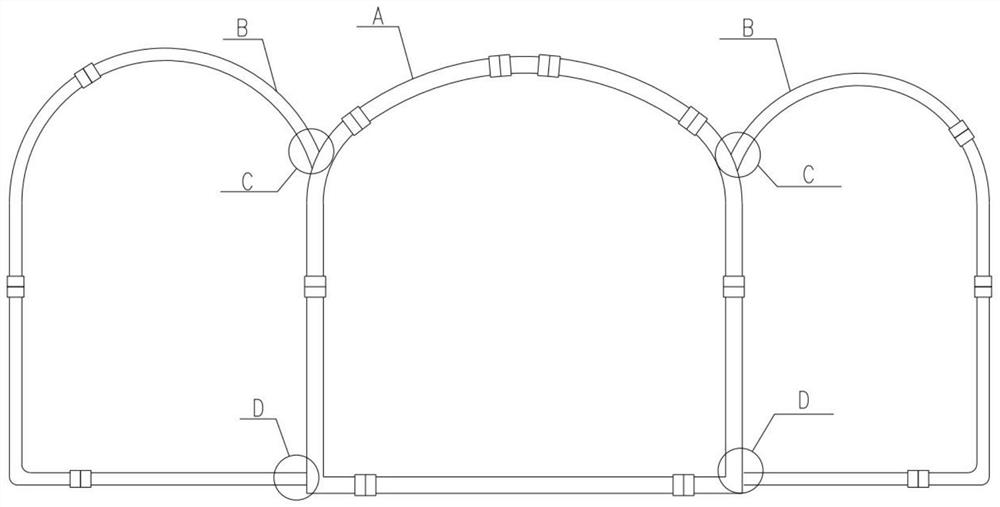
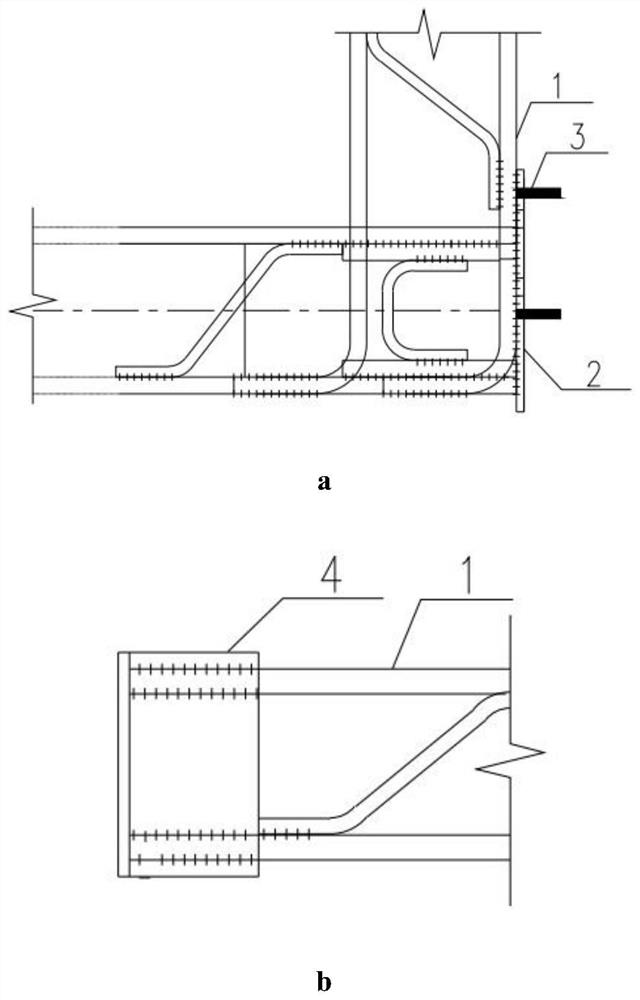
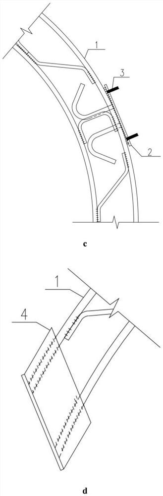
[0026] according to Figure 1 - Figure 5 When using, when the inter-arch mounted positive distribution is constructed, the steel plate 2 is disposed at the first-opening reinforcing reinforced grid main ratio and the adjacent bun, and the steel plate 2 has four reserved holes. The four high-strength bolts 3 is welded to the reserved hole by the plug welding process, and the steel plate 2 is connected firmly to complete the installation of the reinforcement grille; subsequent excavation of the neighboring bin to the co-constructed connection position, in the subsequent excavation of the neighbor The reinforcing grille main ratio 1 is connected to the end head welding firmly two corner steel 4, and four bolt reserved holes 5 are provided on the angle steel 2, and the other end of the four high-strength bolts 3 passes through the bolt reserved hole 5 on the angle steel 4, The nut 6 is tightened, so that the first line opens the bin and subsequent excavation of the neighboring reinforc...


PUM


Abstract

The invention discloses a steel bar grating connecting structure for a multi-arch underground excavation pipe gallery primary support structure and a construction method. A steel plate is arranged onthe outer side of a steel bar grating of a first excavation bin at the connecting position of steel bar gratings of support structures of two adjacent bin primary to serve as an embedded connecting piece; the steel plate is welded with a steel bar grating main rib, and the plane of the steel plate is perpendicular to the connecting direction; anchor bars are arranged on the back of the steel plate, preformed holes and high-strength bolts are symmetrically arranged on the steel plate, the ends of one sides of the bolts are flush with the inner side of the steel plate, and the other sides of thebolts extend outwards to be reserved for being connected with steel bar grating connecting plates of adjacent bins; and two pieces of angle steel are arranged at a co-constructed connecting end partof a corresponding steel bar grating of a subsequent excavation bin, bolt holes are preserved in the angle steel at the positions corresponding to connection with the high-strength bolts, and the angle steel are rapidly and firmly connected with the steel plate as the preserved connecting piece. Compared with an existing construction method, according to the method, the construction progress can be effectively improved, the adjacent bins and an overall co-construction primary support are quickly closed to form a ring, the influence of excavation on a soil body is reduced, and the method has wide development and application prospects in multi-arch underground excavation construction.

Description

Technical field [0001] The present invention relates to a connection structure for the reinforcing grating of the dark privilege gheriff, and more particularly to a primary structure reinforcing structure for the joint form of the dark form, which is easy to might The chamber is connected to the reinforcing grid at the shared initial part. Background technique [0002] The integrated gallery is generally designed as a hydrocontrol, electric warehouse, gas bin and other multicolored form according to the use function. The corresponding hidden rejection segment is generally in the form of the initial joint arch structure, and when the adjacent bin room is interlaced. Taking the form of triple arch structure as an example, it is generally used to use the middle cave method. That is, the middle hole is opened and supported. It is then symmetrically digging the support of both sides of the edge, and the hole of the hole is always opposite the middle hole. That is a certain distance. T...

Claims


Application Information

Patent Timeline
Patent Type & Authority Applications(China)
IPC IPC(8): E21D11/15
CPCE21D11/152
Inventor 宣恒魏盖苏磊刘佳杰宁伟孙德伟孙大伟何明星焦阳
Owner BEIJING MUNICIPAL ROAD & BRIDGE
Why Eureka
Try Eureka