Pedal type computer input device and method

An input device and computer technology, applied in the direction of contact operating parts, etc., can solve the problems that the structure of the pedal switch is not strong enough and the protection effect is not good, and achieve the effect of increasing the protection effect, improving the sturdiness, and improving the efficiency of closing.

Pending Publication Date: 2019-03-22
华研科技(大连)有限公司
View PDF0 Cites 0 Cited by
  • Summary
  • Abstract
  • Description
  • Claims
  • Application Information

AI Technical Summary

Problems solved by technology

[0004] In the process of using the computer, a switch is usually needed, and the computer is turned on and off through the pedal-type input switch signal. The existing pedal switch structure is not strong enough, and the protection effect is not good.

Method used


Image

  • Pedal type computer input device and method
  • Pedal type computer input device and method
  • Pedal type computer input device and method

Examples


Embodiment 1

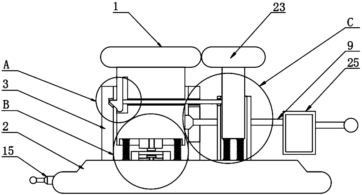
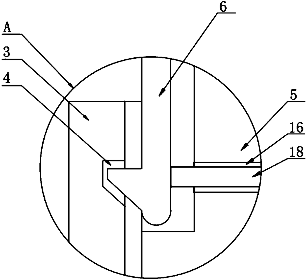
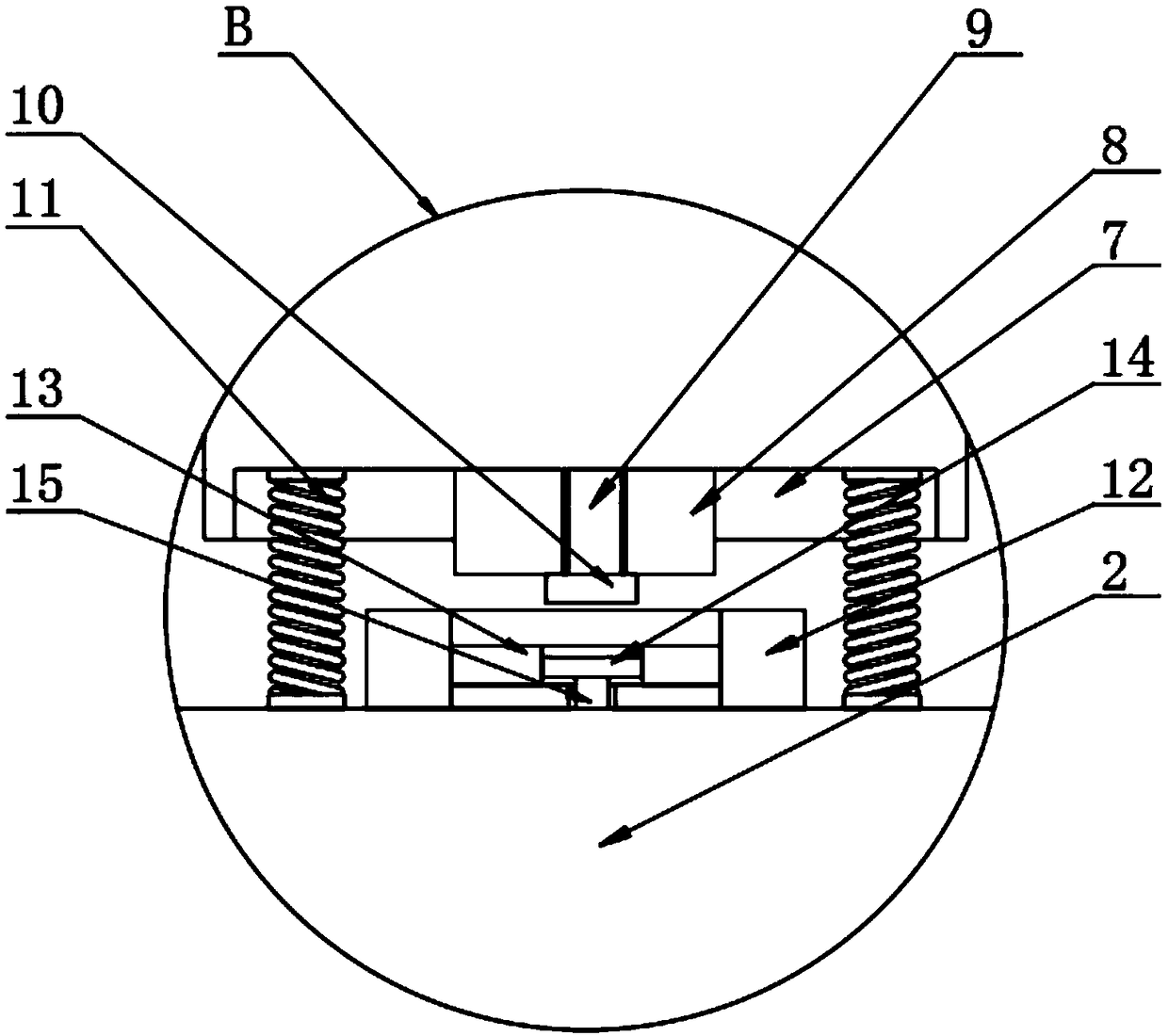
[0029] The present invention provides such Figure 1-6 A pedal-type computer input device shown includes a pedal device 1, the pedal device 1 includes a base 2, the top of the base 2 is provided with a sliding sleeve 3, and the inner wall of the sliding sleeve 3 is provided with a card slot 4, the The inside of the sliding sleeve 3 is provided with a block 5, the surface of the block 5 is provided with a buckle 6, the buckle 6 is matched with the slot 4, the bottom of the block 5 is provided with a groove 7, and the groove 7 is provided with a protective block 8 inside, and the protective block 8 is provided with a live wire 9 inside, and the live wire 9 passes through the clamping block 5 and extends to the outside. The bottom of the live wire 9 is provided with a first connecting block 10, and the protective block 8 Both sides are provided with first springs 11, and the first springs 11 are fixedly connected with the base 2. The bottom of the protective block 8 is provided w...

Embodiment 2

[0039] A pedal-type computer input method, including the pedal-type computer input device, also includes the following steps:

[0040] S1: step on the pressing plate 23 above the clamping block 5, the clamping block 5 slides inside the sliding sleeve 3, and the clamping block 5 drives the buckle 6 to be stuck inside the clamping groove 4;

[0041] S2: The clamping block 5 drives the first connecting block 10 at the bottom of the live wire 9 into the inside of the protective ring 13, so that the first connecting block 10 and the second connecting block 14 come into contact;

[0042] S3: step on the pressing plate 23 on the top of the sliding column 19 when closing, the sliding column 19 slides inside the positioning sleeve 20, and at the same time pull the connecting rope 18 to drive the buckle 6, so that the buckle 6 is disengaged from the inside of the slot 4;

[0043] S4: Afterwards, the first spring 11 pushes the clamping block 5 up, so that the first connecting block 10 an...


PUM


Abstract

The invention discloses a pedal type computer input device and a pedal type computer input method. The pedal type computer input device comprises a pedal device, wherein the pedal device comprises a base, the top part of the base is provided with a sliding sleeve, a clamping groove is formed in the inner wall of the sliding sleeve, a clamping block is arranged inside the sliding sleeve, the surface of the clamping block is provided with a buckle, the buckle is matched with the clamping groove, a groove is formed in the bottom part of the clamping block, the groove is internally provided with aprotection block, a live wire is arranged inside the protection block, the live wire penetrates the clamping block and extends to the outside, the bottom part of the live wire is provided with a first connecting block, first springs are arranged on both sides of the protection block, the first springs are fixedly connected with the base, the bottom part of the protection block is provided with apositioning cylinder, and a protection ring is arranged inside the positioning cylinder. Through arranging the pedal device, the pedal type computer input device effectively isolates and protects thelive wire and a null line, avoids contact of the live wire and the null line when not in use, improves the firmness of the overall structure, increases the protection effect, and avoids the electric shock problem caused by long-term use.

Description

technical field [0001] The invention relates to the field of pedal computer input, in particular to a pedal computer input device and method. Background technique [0002] It can also be used to control the switch of the output current by stepping on or stepping on the operation circuit. The foot switch is a switch that controls the on-off of the circuit by stepping on or stepping on it. In order to replace both hands to achieve the purpose of operation, the operation circuit is switched on and off by stepping or pedaling, and it can also be used to control the switch of the output current. [0003] A foot switch is a switch that controls the on-off of a circuit by stepping or stepping on it. It is used in a control circuit that cannot be touched by both hands to replace both hands to achieve the purpose of operation. The foot switch is used in medical equipment, stamping equipment, welding equipment, textiles, etc. It is widely used in equipment and printing machinery, and...

Claims


Application Information

Patent Timeline
Patent Type & Authority Applications(China)
IPC IPC(8): H01H3/14
CPCH01H3/14
Inventor 白井奎
Owner 华研科技(大连)有限公司
Why Eureka
Try Eureka