
Windscreen wiper drive arrangement

a technology of windscreen wipers and drive shafts, which is applied in the direction of vehicle maintenance, vehicle cleaning, cleaning equipment, etc., can solve the problems of increased wear and increase no longer guaranteed, and increased wear and tear of the internal sealing element, so as to minimize the risk of failure of the seal

Inactive Publication Date: 2009-04-16
ROBERT BOSCH GMBH
View PDF9 Cites 9 Cited by
  • Summary
  • Abstract
  • Description
  • Claims
  • Application Information

AI Technical Summary

Benefits of technology

[0004]The object of the invention is to provide an improved wiper drive arrangement in which the risk of failure of the seal is minimized.
[0007]According to an advantageous embodiment of the invention, the protective sleeve and a portion of the gear mechanism housing, preferably a fixing dome of the gear mechanism housing, engage in a mutually interlocking manner. As a result of this positive connection, a rotation of the protective sleeve relative to the gear mechanism housing is avoided. In addition to this securing against a movement in the peripheral direction, the protective sleeve may be secured against an axial movement. To this end, the axial fixing may, for example, be produced by a further positive connection of the protective sleeve with the gear mechanism housing. A support of the protective sleeve in the axial direction on a component supported on the drive shaft, in particular a speed nut, or a radial portion configured integrally with the drive shaft is also conceivable.

Problems solved by technology

As a result of external influences, in particular as a result of continuous shaking movements during travel or during repair work, however, the frictional connection between the protective sleeve and the gear mechanism housing may be released, which may result in the protective sleeve being able to move in the axial direction and / or in the peripheral direction.
As a result, firstly there is the risk that the protective sleeve during operation of the windscreen wiper moves in an oscillating manner together with the drive shaft, which leads to greater wear of the internal sealing element.
Moreover, the protective sleeve may become skewed such that an effective seal relative to the drive shaft and / or relative to the vehicle component, through which the drive shaft is guided, is no longer ensured.
It leads to water ingress, in particular into the gear mechanism and / or motor housing and thus to increased occurrence of wear and an electrical short circuit.

Method used


Image

  • Windscreen wiper drive arrangement
  • Windscreen wiper drive arrangement
  • Windscreen wiper drive arrangement

Examples


Embodiment Construction

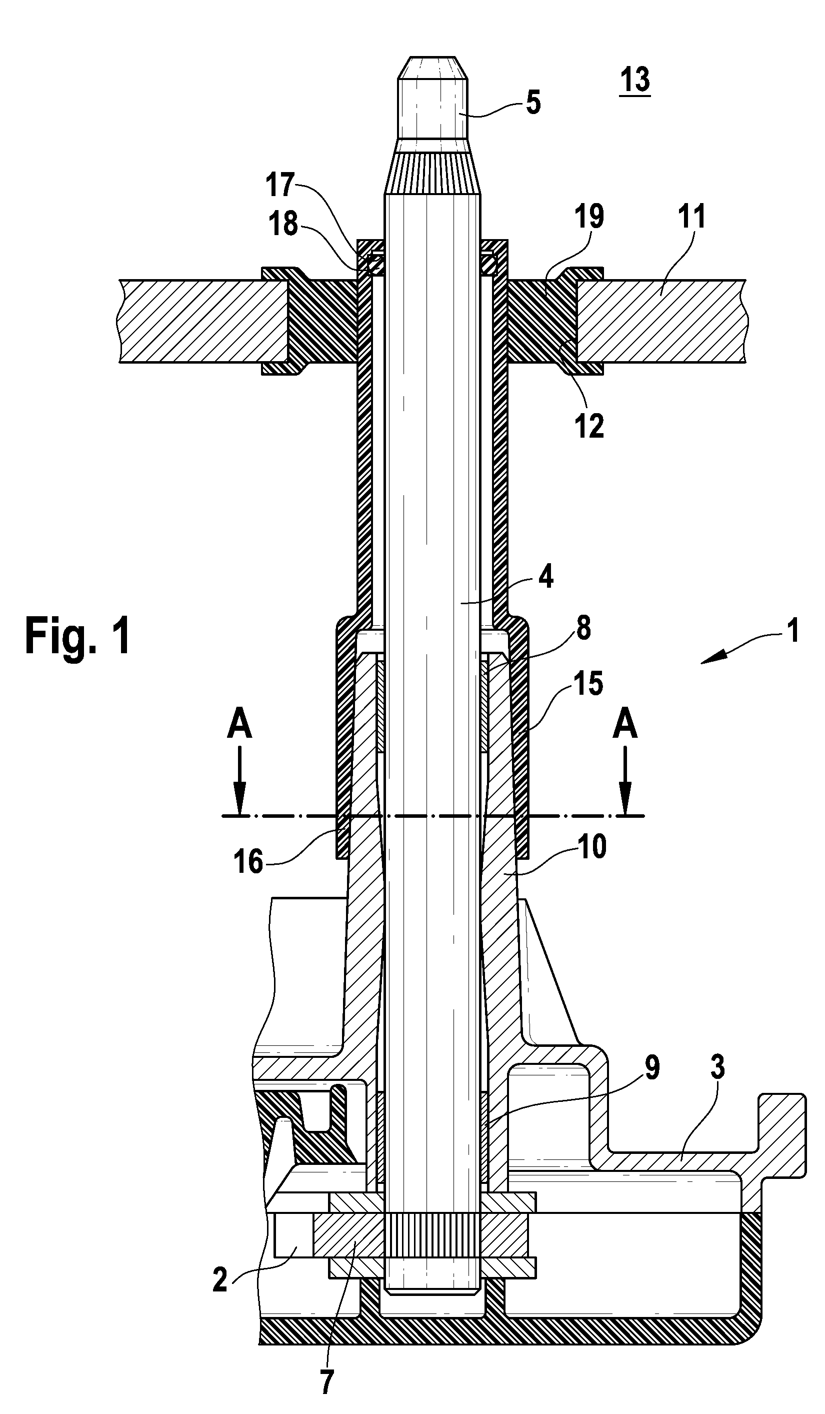
[0030]The same components and components with the same function are identified in the figures by the reference numerals.

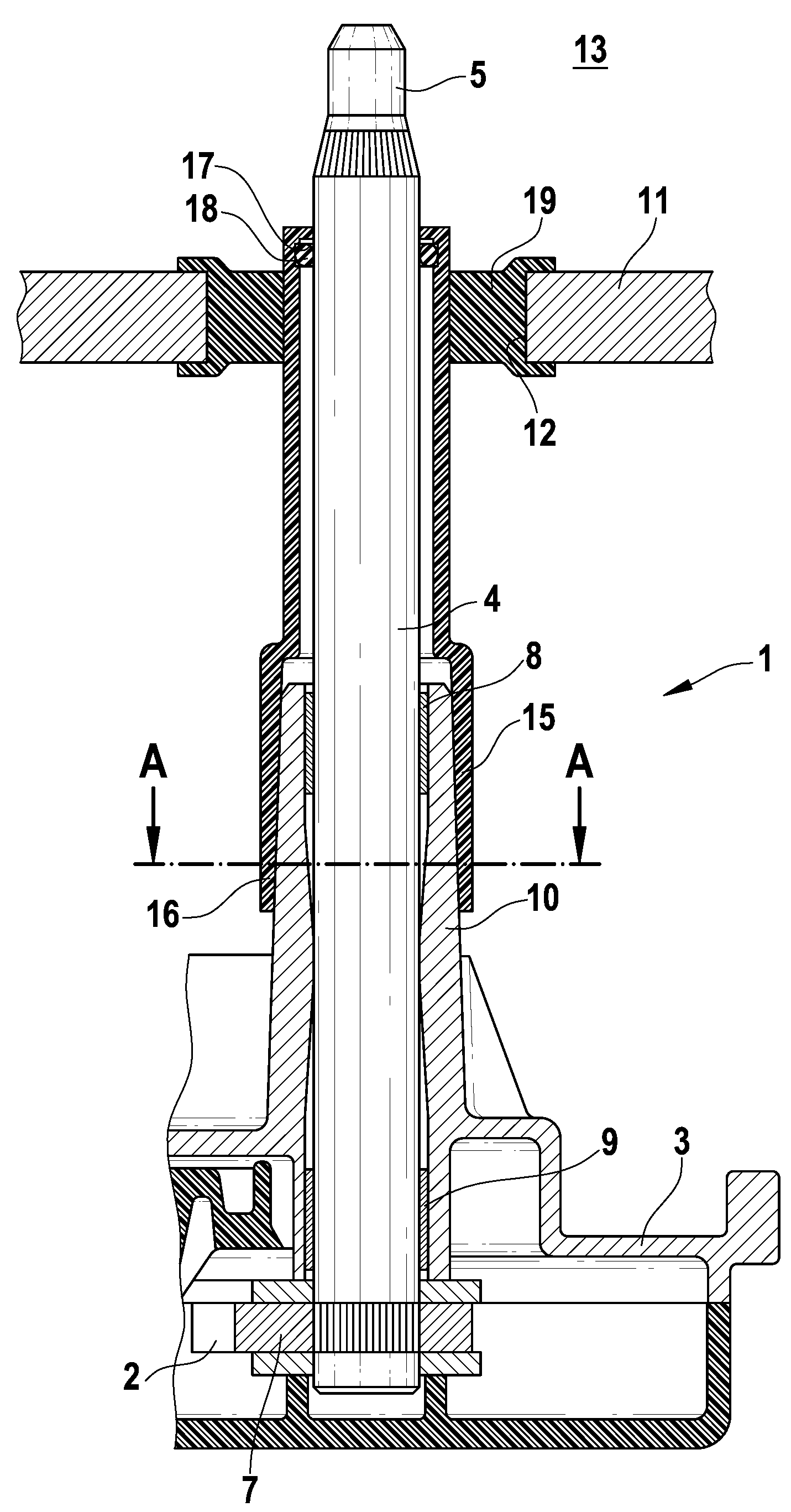
[0031]In FIG. 1 a windscreen wiper drive arrangement 1 is shown for a motor vehicle. An electric drive motor, not shown, is connected to a gear mechanism 2 via an output shaft, also not shown. The partially shown gear mechanism 2 is arranged inside a partially shown gear mechanism housing 3 made of aluminum. By means of the motor and the gear mechanism 2, a drive shaft 4 is driven in an oscillating manner. A wiper arm may be fixed to the free end 5 of the drive shaft 4 guided out of the gear mechanism housing 3. On the drive shaft 4 is located a gear wheel 7 which meshes with a toothed element of the gear mechanism 2. The drive shaft 4 is mounted by means of two spaced-apart bearings 8, 9 inside the gear mechanism housing 3 in the axial direction as well as in the radial direction. The front bearing 8 is located in a fixing dome 10 of the gear mechanism housing 3 w...


PUM


Abstract

The invention relates to a windscreen wiper drive arrangement (1) having a drive shaft (4), extending out of a gear mechanism housing (3), for a windscreen wiper, in which the drive shaft (4) is guided axially through a protective sleeve (15) which is sealed with respect to the drive shaft (4) by means of at least one inner sealing element (18) and with respect to a vehicle component (11) by means of at least one outer sealing element. The invention provides for the protective sleeve (15) to be secured to the gear mechanism housing in order to protect said protective sleeve against axial movement in the direction of the vehicle component (11) and / or against rotational movement relative to the gear mechanism housing (3) by frictional engagement and / or by means of at least one separate securing element (25).

Description

BACKGROUND OF THE INVENTION[0001]The invention relates to a windscreen wiper drive arrangement.[0002]A windscreen wiper drive arrangement is known from DE 299 01 686 U1 comprising a drive motor which is connected via an output shaft to a gear mechanism arranged in a gear mechanism housing. Guided out of the gear mechanism housing is a drive shaft for a windscreen wiper which is driven in an oscillating manner. Conventionally, the drive shaft is guided through an opening in the bodywork or a window, generally the rear window. To avoid water ingress, conventionally a protective sleeve is provided through which the drive shaft is guided in the axial direction. Said protective sleeve is sealed relative to the drive shaft by means of an internal sealing element, for example an O-ring, so that no water is able to run toward the interior along the drive shaft. Moreover, the protective sleeve is sealed by means of an external sealing element, in particular a so-called grommet, relative to t...

Claims


Application Information

Patent Timeline
Patent Type & Authority Applications(United States)
IPC IPC(8): B60S1/26
CPCB60S1/349B60S1/06B60S1/583B60S1/3493B60S1/32B60S1/34
Inventor REITH, MICHAELALBRECHT, GERARDLIPPS, VERENABOHN, ROLANDHUESGES, MARIOFRIDERICHS, GUENTHERGEUBEL, PAUL
Owner ROBERT BOSCH GMBH
Learn More