Supercharge Your Innovation With Domain-Expert AI Agents!

Sliding contact switch

a contact switch and sliding technology, applied in the direction of contacts, contact surface shape/structure, contact mechanisms, etc., can solve the problems of not being able to form and it is not possible to produce a conducting connection between the selective contact body and the electrical connection cannot be produced. to achieve the effect of increasing the resistance to further movemen

Inactive Publication Date: 2009-04-16
ZF FRIEDRICHSHAFEN AG
View PDF9 Cites 14 Cited by
  • Summary
  • Abstract
  • Description
  • Claims
  • Application Information

AI Technical Summary

Benefits of technology

[0013]Even though the shape of the rib can, to a large degree, be freely determined, it is still necessary to ensure that the sliding contact and the rib are configured such that at the instant in which the sliding contact touches the rib and is not yet raised from the sliding area there is a gap between sliding contact and rib base and the sliding contact cannot penetrate into this gap. As indicated in the foregoing, this gap interrupts the sliding track between the selective contact bodies and in addition lubrication grease or oil can collect in this gap and thus improve lubrication of the sliding contact. Lubrication grease used will preferably collect at base of the rib and distribute along the rib so that lubrication oil or grease for lubricating the sliding contact can be picked up each time the sliding contact passes by.
[0014]That which was described in the foregoing using the example of a rib in the switching area of the housing also applies analogously and likewise for grooves that are added to the sliding area. In contrast to the embodiment with ribs that project from the sliding area, in which embodiment the sliding path is interrupted on both sides of the rib, when a groove is added to the sliding area the sliding path is interrupted only once. At the base of the groove, which the sliding contact does not touch, there is no mechanical contact with the sliding contact and thus here as well there can be no melting of the abrasion, creating a conducting path. The shape of the groove can be selected as desired as long as it is ensured that the sliding contact cannot penetrate into the groove base.
[0016]Adding grooves or ribs also results in the additional advantage of tactile feedback that occurs when the sliding contact passes over the groove or rib. This can be used for discerning a switching state, for instance a base position for the switch. This is particularly simple given a constriction, because the sliding contacts are pressed slightly into the concavity due to the pressing force and it is possible to perceive an increase in the resistance to further movement by the sliding contacts.
[0017]Thus, for instance, a center zero position is possible that can be a base position for the switch. But such an effect can also be attained by arranging two ribs one after the other. In this case, when the sliding contact crosses the first rib, the tactile feedback can be used to determine a non-conducting position of the sliding contact after leaving the selective contact and, conversely, a conducting connection on a selective contact body can be detected after leaving the sliding area. Thus, a switch position having a conducting electrical connection or a position having a non-conducting connection can be determined in a simple and reliable manner. Thus, for instance, the non-conducting sliding area, also called an insulator, is arranged in a so-called center zero position between two conducting areas, each of which are associated with a selective contact body or even belong to just a single contact body (selective contact body). In the center zero position, the sliding contact of the contactor is located in the sliding area of the insulator, so that no passage occurs in the switch.

Problems solved by technology

Thus, it is not possible for an electrical connection to be produced between the selective contact bodies by deposits that can be metal abrasion from the sliding contacts and / or can be soilage.
Because of this an interruption occurs in the sliding path on each side of the rib, and abrasion and / or soilage cannot produce any conducting connection in this interruption.
Thus, it is simply not possible to form a conducting connection between the selective contact bodies via the rib.

Method used


Image

  • Sliding contact switch
  • Sliding contact switch
  • Sliding contact switch

Examples


Embodiment Construction

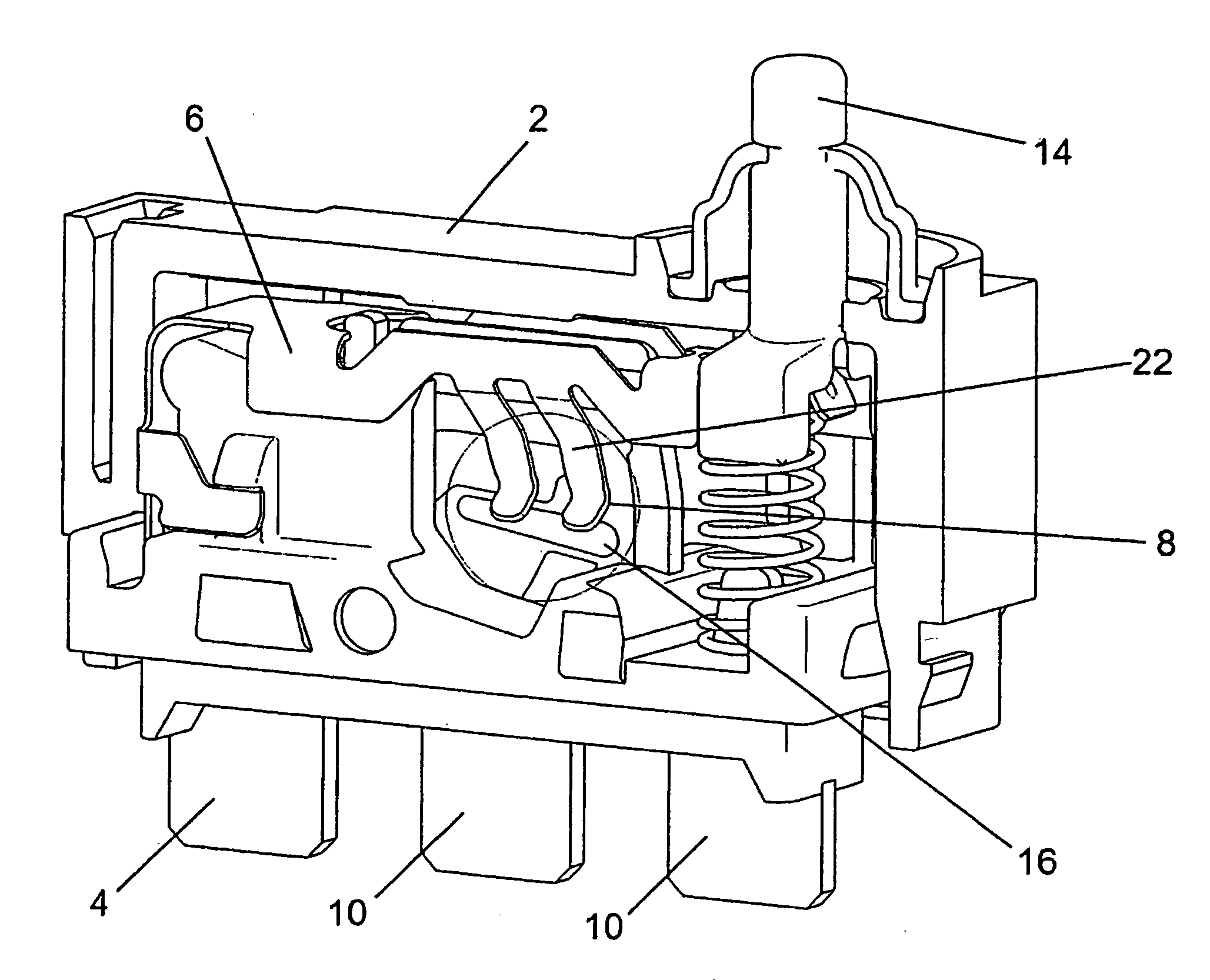
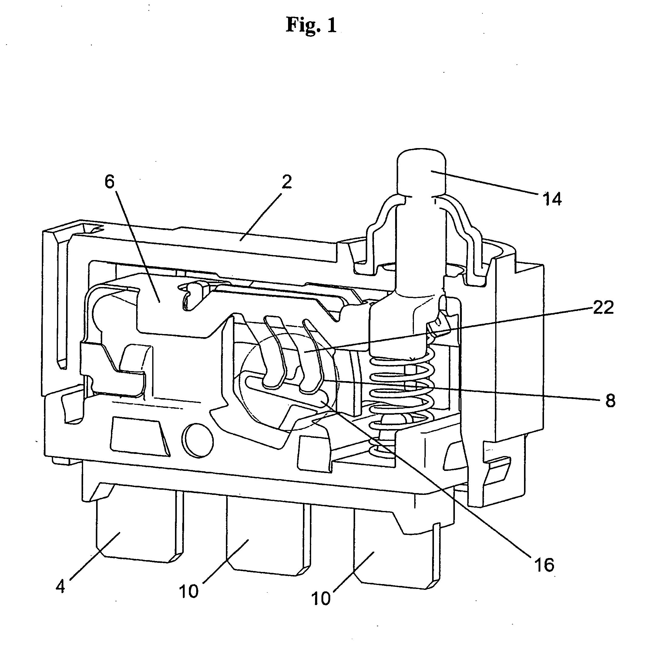
[0029]FIG. 1 depicts a sliding contact switch as it is known from the aforesaid prior art, but with a rib added to the sliding area. The switch depicted has a housing 2 in which a common contact body 4 and two selective contact bodies 10 are arranged with their broad sides flat adjacent to one another such that one end of each of the three contact bodies projects from the housing. In the housing 2, the common contact body 4 and the two selective contact bodies 10 are arranged or embedded in the housing 2 such that there is no conducting connection between them. A contactor 6 is in continuous electrical conducting connection with the contact body 4. The contactor can be switched back and forth elastically between the contact surfaces 11 of the selective contact bodies 10 using an actuating member 14. The contact surfaces 11, which are disposed on both sides of the selective contact bodies 10, are enclosed, elastically pre-stressed, by contact fingers 22 that are disposed on the conta...


PUM


Abstract

An electrical sliding contact switch having a housing in which a common contact body and at least one selective contact body having a contact surface are arranged. A sliding area including electrically insulating material is arranged adjacent to the contact area of the selective contact body. A contactor that is in continuous electrically conducting connection with the common contact body and has at least one sliding contact is either in electrically conducting connection with the selective contact body or touches the sliding area. An actuating member is furthermore arranged in the housing such that upon actuation, it slidingly moves the at least one sliding contact of the contactor on a sliding path from the contact surface of the selective contact body into the sliding area and / or out of the sliding area to the contact surface of the selective contact body. Furthermore, embodied in the sliding path, are zones that are not touched by the sliding contacts during transit of the sliding area.

Description

BACKGROUND OF THE INVENTION[0001]The invention relates to an electrical sliding contact switch, in particular, a microswitch, miniature switch, or subminiature switch, the switch positions of which are changed by sliding movement by the contact body.[0002]Electrical sliding contact switches of this type act as microswitches, miniature switches, or subminiature switches in many application fields such as, for example, in automobile instrument engineering and household appliances. In these switches, sliding contacts are brought from one contact point to another contact point in a sliding movement. The electrically conducting connection is only meant to occur at the respective contact points.[0003]Known from DE 10 2006 011 930 B3, is an electrical sliding contact switch having a pivotably borne contact rocker. The known switch has a base made of an electrically insulating plastic and a cover. The voltage is applied to a common contact body that is continuously in electrically conductin...

Claims


Application Information

Patent Timeline
Patent Type & Authority Applications(United States)
IPC IPC(8): H01H3/00
CPCH01H1/36H01H1/40H01H2001/406H01H13/64H01H1/42
Inventor RUFF, EDUARD
Owner ZF FRIEDRICHSHAFEN AG
Features
  • R&D
  • Intellectual Property
  • Life Sciences
  • Materials
  • Tech Scout
  • Unparalleled Data Quality
  • Higher Quality Content
  • 60% Fewer Hallucinations
Learn More