
Locking device for the door of an apparatus comprising a rotary drum, and a latch for such device

Active Publication Date: 2009-04-16
GIRBAU SA
View PDF9 Cites 9 Cited by
  • Summary
  • Abstract
  • Description
  • Claims
  • Application Information

AI Technical Summary

Benefits of technology

[0009]According to a first aspect, the present invention contributes to reach the previous and other objectives by providing a locking device for the door of an apparatus comprising a rotary drum, of the type comprising a latch which is pivotingly mounted on a moving leaf of said door, and a control box which is attached to the fixed frame of the door, said control box being configured to receive and lock a tip of said latch. The device is characterized in that said tip of the latch acts primarily as a control tip and the latch comprises at least one second tip acting as a coupling tip configured to be coupled in a retaining stop.
[0010]The control box comprises a passage to receive therethrough said control tip, and said coupling tip is spaced apart from the control tip and is configured such that it can be coupled in said retaining stop, which is in a spaced apart position from the passage of the control box. If considered convenient, there is no technical obstacle for said retaining stop to be independent of the control box. When the latch is in the coupling position, the coupling configuration of the coupling tip has a contact surface parallel to a corresponding contact surface of said retaining stop and substantially perpendicular to the direction of an opening force generated by at least one elastic joint compressed between said leaf and the frame of the door.
[0011]In one exemplary embodiment, the latch is pushed by at least one elastic element to a coupling position, and the mentioned control box comprises, apart from the mentioned passage, at least one cam profile located next to said passage so as to move said tip of the latch against the thrust of said elastic element at the time of its introduction; a slide with an opening arranged for the passage of said tip of the latch therethrough, said slide being configured to be moved in relation to the control box by the latch between an open position and a closed position; a detection device configured to detect the slide in said closed position; and an immobilizing device operated by an electrically or electronically controlled actuator and configured to immobi

Problems solved by technology

Nevertheless, when said devices are used in larger industrial machines, the coupling capability of the latch is not able to withstand forces of up to 200 N which the compressed elastic joints can get to exert in these cases.
Also, given that in these types of devices the latch performs both a control function and a coupling function, a re-dimensioning and modification of the configuration of the latch to ensure its coupling capability can result in a worsening of the control function, apart from resulting in a significant increase in the size of the passage, the slide and, all in all the entire assembly of the control box.
However, this British patent does not describe or suggest the use of two latches or of a latch with two tips to ensure the coupling capability without affecting the control function.

Method used


Image

  • Locking device for the door of an apparatus comprising a rotary drum, and a latch for such device
  • Locking device for the door of an apparatus comprising a rotary drum, and a latch for such device
  • Locking device for the door of an apparatus comprising a rotary drum, and a latch for such device

Examples


Embodiment Construction

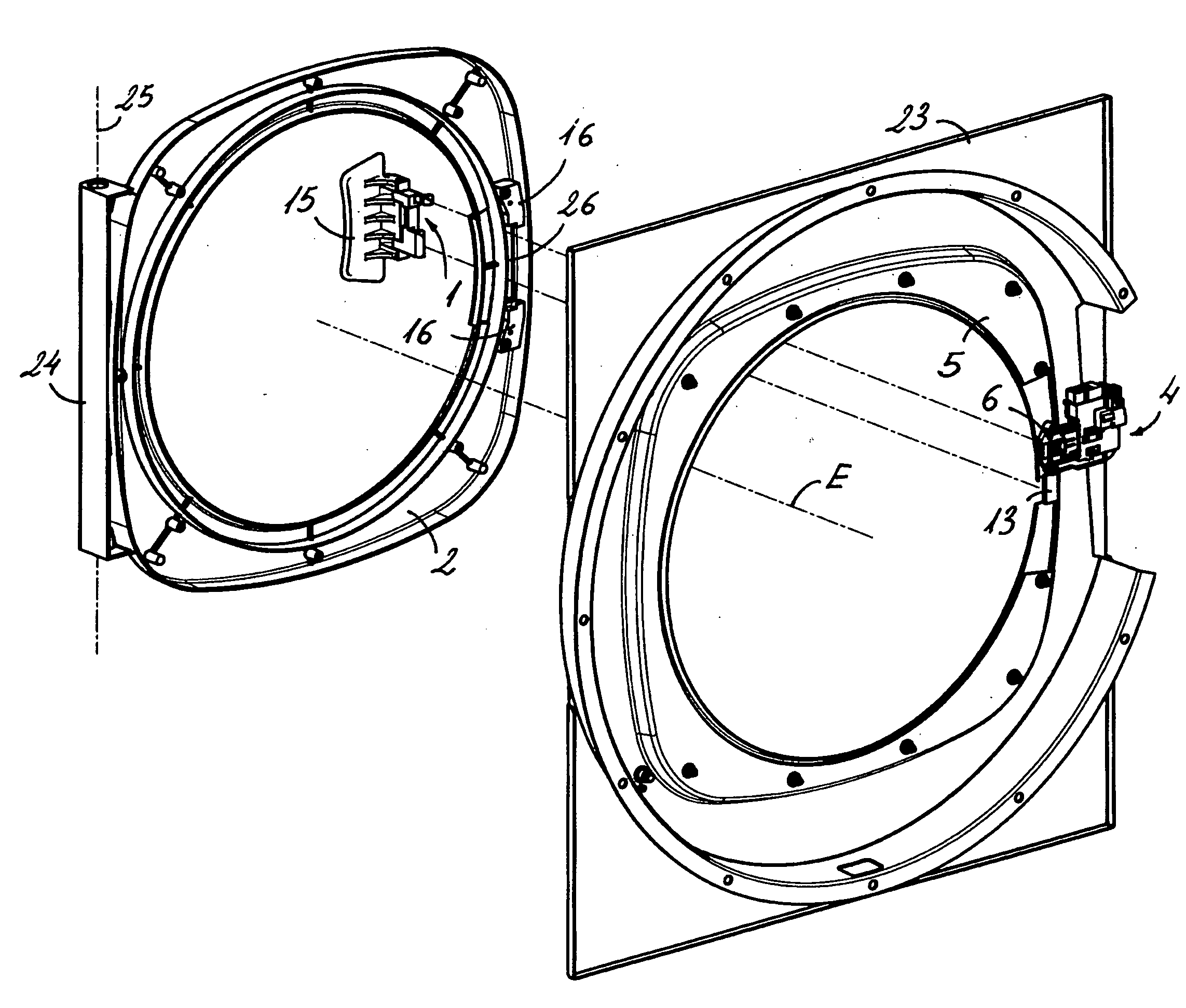
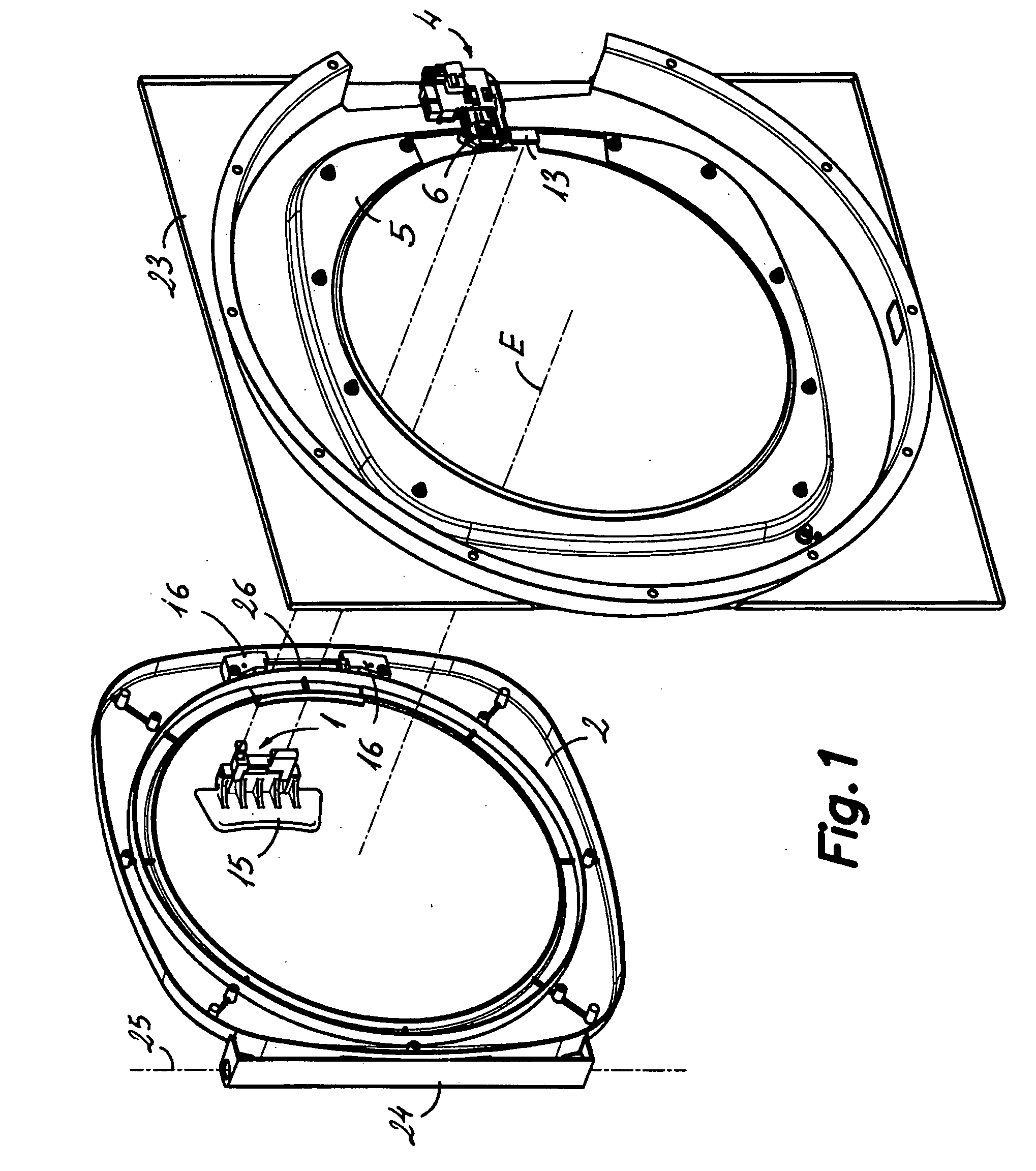
[0023]With reference first to FIG. 1, the device according to an embodiment of the present invention is shown in relation to a moving leaf 2 and a fixed frame 5 of a door of an apparatus comprising a rotary drum, such as industrial type washing-spinning machine. In this illustrated exemplary embodiment, the apparatus is of the type comprising a drum (not shown) having a substantially cylindrical shape and arranged to rotate around a horizontal shaft aligned with shaft E of FIG. 1. The drum has a concentric circular orifice arranged in a front wall thereof. A door defined by a circular fixed frame 5, centered in relation to shaft E is arranged in a front panel 23 of the apparatus. The fixed frame 5 conventionally includes at least one or more reinforcing plates around the opening of the door in the front panel 23. The mentioned door has a moving leaf 2 assembled on the front panel 23 by means of a hinge device, 24 arranged in a side of the moving leaf 2 and of the fixed frame 5, such...


PUM


Abstract

The invention relates to a locking device for the door of an apparatus comprising a rotary drum, and to a latch for one such device. The inventive device comprises a latch articulated to a moving leaf of the door, and a control box attached to a fixed frame of the door and configured to receive and immobilize the tip of the latch into a passage provided therein. The aforementioned tip acts primarily as a control tip. The latch comprises at least one second tip acting as a coupling tip which is spaced apart from the control tip and which is configured such that it can be coupled in a retaining stop that is attached to the fixed frame of the door in a position spaced apart from the passage in the control box.

Description

TECHNICAL FIELD[0001]The present invention generally relates to a locking device for the door of an apparatus comprising a rotary drum, such as a washing, spinning or drying, machine and more specifically though not exclusively to a locking device for the door of an apparatus comprising a rotary drum with an axial loading aperture. The present invention also relates to a latch for such device.STATE OF THE PRIOR ART[0002]Electrical household or industrial appliances, such as washing machines, spinning machines, dryers, or combinations thereof, comprising a rotary drum adapted to house the items to be treated and assembled to rotate partially submerged in a liquid contained in a tub enclosed in a protective casing. In a classic arrangement, the drum is cylindrical and rotates about a horizontal shaft. For the access to the inside of the drum, both a wall of the drum and the casing include respective doors or openings. There are generally two alternative constructions. According to one...

Claims


Application Information

Patent Timeline
IPC IPC(8): E05C3/14
CPCF16P3/08D06F37/42Y10T292/1059Y10T292/108Y10T292/1048Y10T292/0945Y10T292/0923Y10T292/0921Y10T292/0932Y10T292/1047Y10T292/0926Y10T292/1051Y10T292/1044D06F34/20
Inventor SANS ROVIRA, RAMONMAS GILI, JORDIRIERA CURCOLL, IGNASIVILLAR FEBRE, JAUME
Owner GIRBAU SA
Learn More