Acoustic system for providing individual acoustic environment

a technology of acoustic environment and acoustic system, which is applied in the field of acoustic system, can solve the problems of deteriorating leakage reduction accuracy, difficult listening with a realistic sense, and inability to perform highly accurate sound leakage reduction control

Inactive Publication Date: 2009-04-16
FUJITSU GENERAL LTD
View PDF9 Cites 20 Cited by
  • Summary
  • Abstract
  • Description
  • Claims
  • Application Information

AI Technical Summary

Problems solved by technology

However, if a listener does not use a headset, leak sound or noise from other seats causes a problem.
However, when the error path transfer function presumed in advance is used, there is a problem that, when a sound field environment is changed between the time of presumption and the time of control, reduction accuracy of the leak sound deteriorates.
However, because the path transfer function used at the time of control is not for the sound field environment at the time of control, highly accurate sound-leakage reduction control cannot be performed.
However, when an individual acoustic environment is provided in a car, the speaker and the error microphone need to be installed on a self seat due to a safety reason such as not blocking the visibility of a driver.
However, if the speaker is installed on the self seat, the listener hears the sound from the back, thereby causing a problem such that a sound image is localized at the back, and listening with a realistic sense becomes difficult.

Method used


Image

  • Acoustic system for providing individual acoustic environment
  • Acoustic system for providing individual acoustic environment
  • Acoustic system for providing individual acoustic environment

Examples


first embodiment

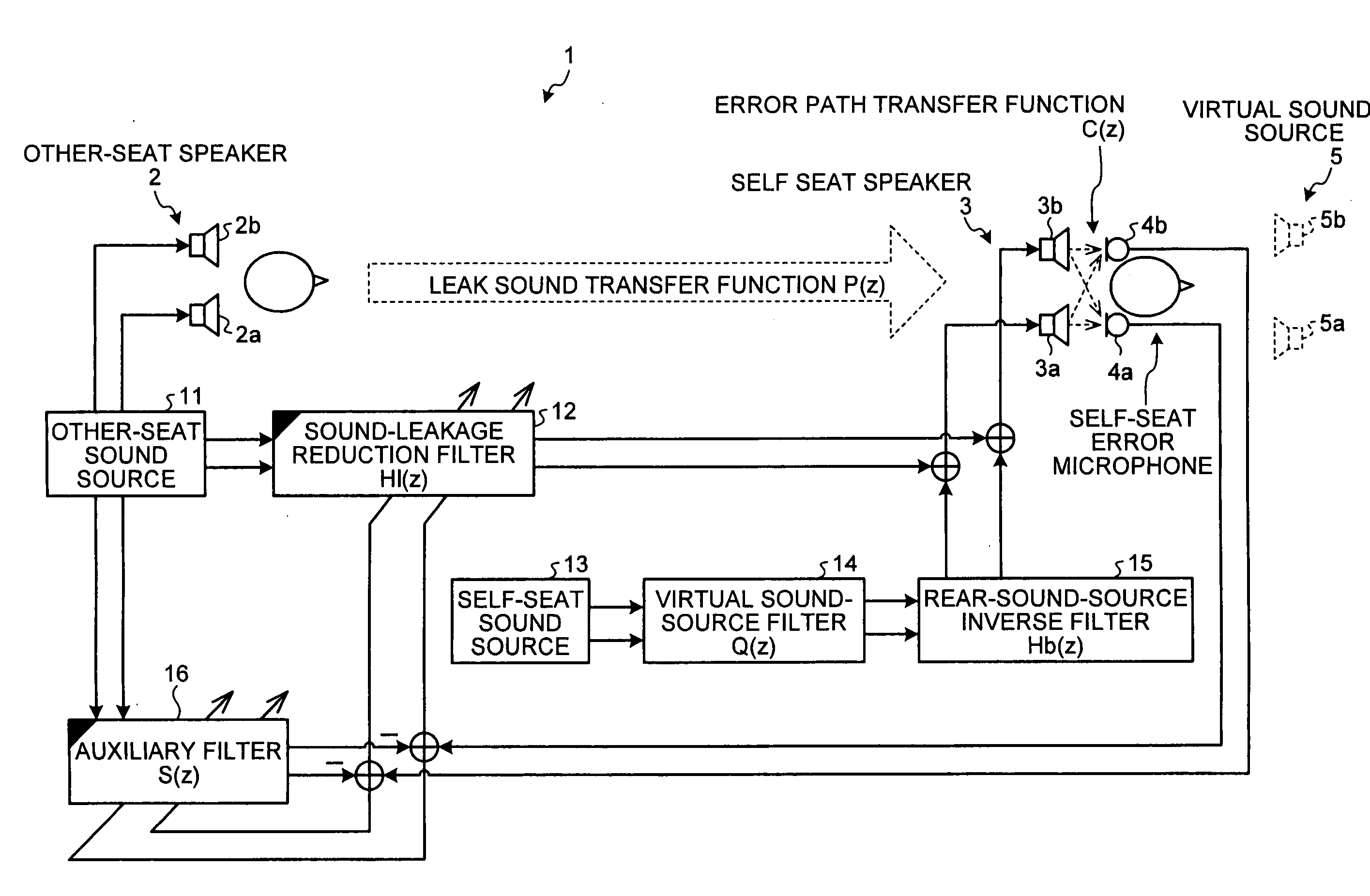
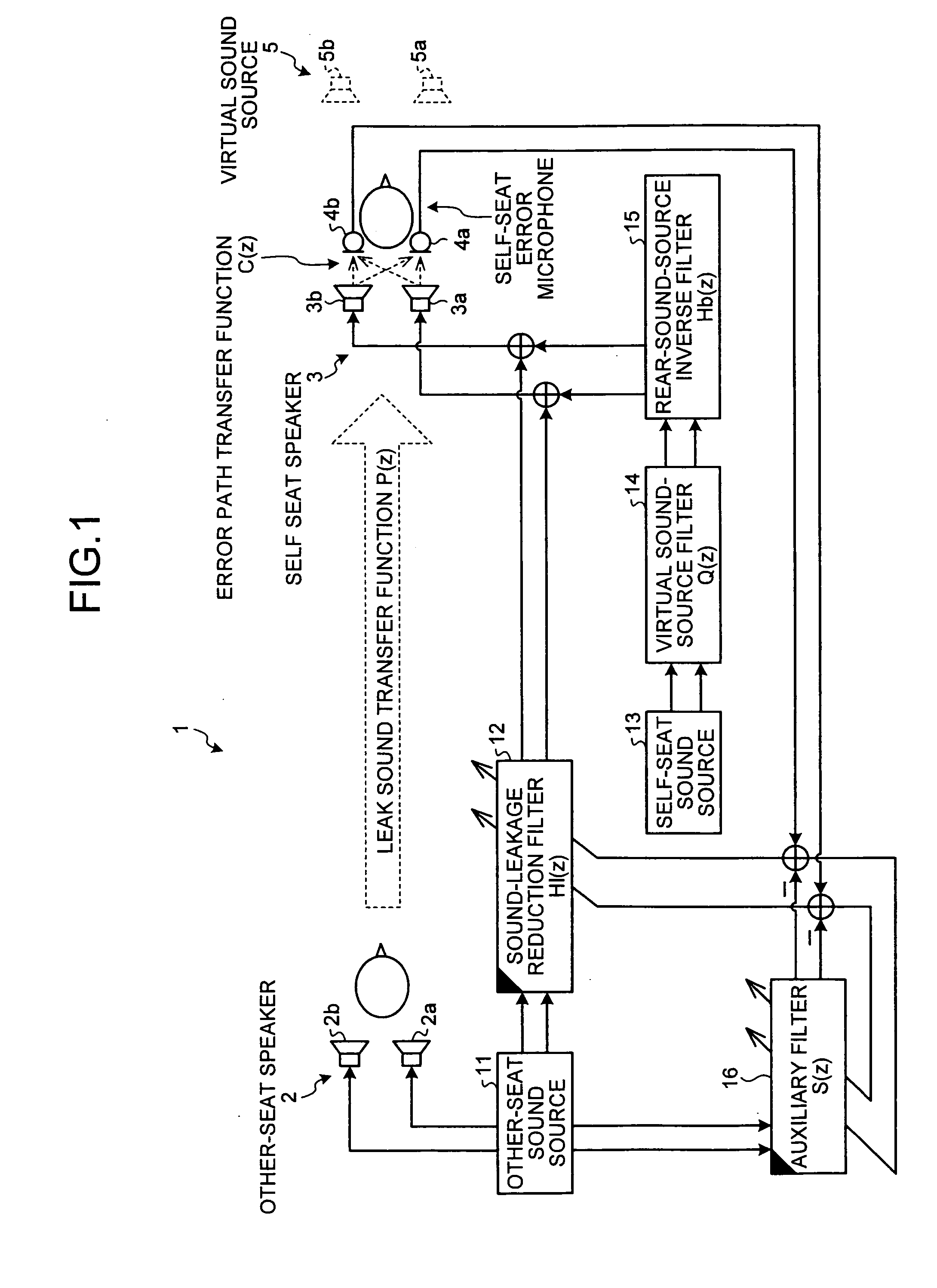
[0023]FIG. 1 is a schematic diagram of a configuration of an acoustic system according to a As illustrated in FIG. 1, an acoustic system 1 includes an other-seat speaker 2, a self seat speaker 3, a self-seat error microphone 4, an other-seat sound source 11, a sound-leakage reduction filter 12, a self-seat sound source 13, a virtual sound-source filter 14, a rear-sound-source inverse filter 15, and an auxiliary filter 16. The sound provided from the self seat speaker 3 has a virtual sound image in front of a listener on a self seat (see “virtual sound source 5” in FIG. 1). Filters indicated in black at an upper left corner (the sound-leakage reduction filter 12 and the auxiliary filter 16) express that these filters are ADFs (adaptive digital filters).

[0024]As illustrated in FIG. 1, the acoustic system 1 according to the first embodiment dynamically presumes a leak sound transfer function P(z) between the other-seat speaker 2 and the self-seat error microphone 4 and an error path t...

second embodiment

[0065]As illustrated in FIG. 5, the acoustic system 1 dynamically presumes the leak sound transfer function P(z) between the other-seat speaker 2 and the self-seat error microphone 4 and the error path transfer function C(z) between the self seat speaker 3 and the self-seat error microphone 4 to effectively reduce the sound leaked from the other-seat speaker 2 to the listener on the self seat, and localizes the sound generated from the self seat speaker 3 in front of the listener as indicated by the virtual sound source 5, to provide an individual acoustic environment with a realistic sense.

[0066]Thus, by providing the leak sound transfer function P(z) and the error transfer function C(z) dynamically presumed by the auxiliary filter (first auxiliary filter) 16 to the sound-leakage reduction filter 12, and by providing the error transfer function C(z) dynamically presumed by the auxiliary filter (second auxiliary filter) 17 to the rear-sound-source inverse filter 15, the accuracy of...


PUM


Abstract

An acoustic system uses a self speaker installed to be at the back of a listener in a first individual space and an error microphone installed to be closer to the listener than the self speaker. A sound-leakage reduction filter generates control sound for negating sound leaked from another speaker installed in a second individual space to the first individual space, and provides the control signal to the self speaker. A virtual sound-source filter generates a virtual sound source, and a rear-sound-source inverse filter corrects rearward localization of a sound image toward the listener.

Description

CROSS-REFERENCE TO RELATED APPLICATIONS[0001]The present application claims priority to and incorporates by reference the entire contents of Japanese priority documents 2007-265865 and 2007-265866 filed in Japan on Oct. 11, 2007.BACKGROUND OF THE INVENTION[0002]1. Field of the Invention[0003]The present invention relates to an acoustic system for providing an individual acoustic environment with respect to each individual space in a predetermined space, and, more particularly to an acoustic system that can effectively reduce sound leakage from other seats even if there is an environmental change or a change with time, and that can provide an individual acoustic environment with a realistic sense while not blocking visibility of a listener.[0004]2. Description of the Related Art[0005]An acoustic system for providing a different acoustic environment for each seat has been known in vehicles such as airplanes, trains, and cars. However, if a listener does not use a headset, leak sound o...

Claims


Application Information

Patent Timeline
Patent Type & Authority Applications(United States)
IPC IPC(8): G10K11/16
CPCG10K11/178H04R27/00H04R5/02G10K2210/3019G10K2210/1281G10K2210/111G10K11/17854G10K11/17813G10K11/17857G10K11/17879G10K11/17885
Inventor KAMIYA, MASAHIRO
Owner FUJITSU GENERAL LTD
Why Eureka
Try Eureka