Transfer belt unit and image forming apparatus using the same

a technology of image forming apparatus and transfer belt, which is applied in the direction of electrographic process apparatus, instruments, optics, etc., can solve the problems of inability to transfer, prone to cohesion of toner itself, and degradation of graininess, so as to reduce the cohesion of toner, improve the durability, and reduce the effect of cohesion

Inactive Publication Date: 2009-04-16
SHARP KK
View PDF17 Cites 13 Cited by
  • Summary
  • Abstract
  • Description
  • Claims
  • Application Information

AI Technical Summary

Benefits of technology

[0028]In accordance with the fifth aspect of the present invention, in addition to the above effect of the first to fourth aspects, it is possible to secure a large curvature at the bend of the intermediate transfer medium, hence improve its durability.
[0029]In accordance with the sixth aspect of the present invention, it is possible to suppress toner cohesion when the toner image is transferred to the belt-like intermediate transfer medium (at the primary transfer) and hence perform fair transfer of the toner image from the belt-like intermediate transfer medium to recording medium such as recording paper etc. (at the secondary transfer).
[0030]Further, it is also possible to cut down the cost for the materials of the intermediate transfer medium etc.
[0031]In accordance with the seventh aspect of the present invention, in addition to the above effect of the sixth aspect, it is possible to enhance the above effect on the toner that is prone to cohere at the primary transfer.
[0032]In accordance with the eighth aspect of the present invention, in addition to the above effect of the sixth and seventh aspects, it is possible to further enhance the above effect on the toner that is prone to cohere at the primary transfer.
[0033]In accordance with the ninth aspect of the present invention, in addition to the above effect of the sixth to eighth aspects, it is possible to further enhance the above effect since increase in the nip pressure acting on the toner as the layers of toner are laminated one over another during the first transfer stage can be suppressed.

Problems solved by technology

However, when thick recording paper etc. having raggedness is used as the recording medium, there have been the problems of transfer failures occurring such as void printed characters, degradation of graininess (density irregularity occurring in high spatial frequency) in a so-called solid image area having totally high density and degradation of mottle (density irregularity occurring in low spatial frequency).
As a result, however, there occurs the problem that the toner itself is prone to cohere due to slight pressure or heat.
That is, when a toner that is high in cohesiveness is used with a conventional intermediate transfer belt having a thickness of 70 μm or greater, which has been usually used, toner cohesion is prone to occur at the primary transfer because the pressing force is too high.
As a result, the performance of the secondary transfer degrades.
However, in this case, if the toner is poor in fluidity (high in cohesiveness), there occurs a new problem that the secondary transfer performance lowers to thereby cause degradation of final image quality.

Method used


Image

  • Transfer belt unit and image forming apparatus using the same
  • Transfer belt unit and image forming apparatus using the same
  • Transfer belt unit and image forming apparatus using the same

Examples


Embodiment Construction

[0046]The embodiment of the present invention will hereinafter be described in detail with reference to the accompanying drawings.

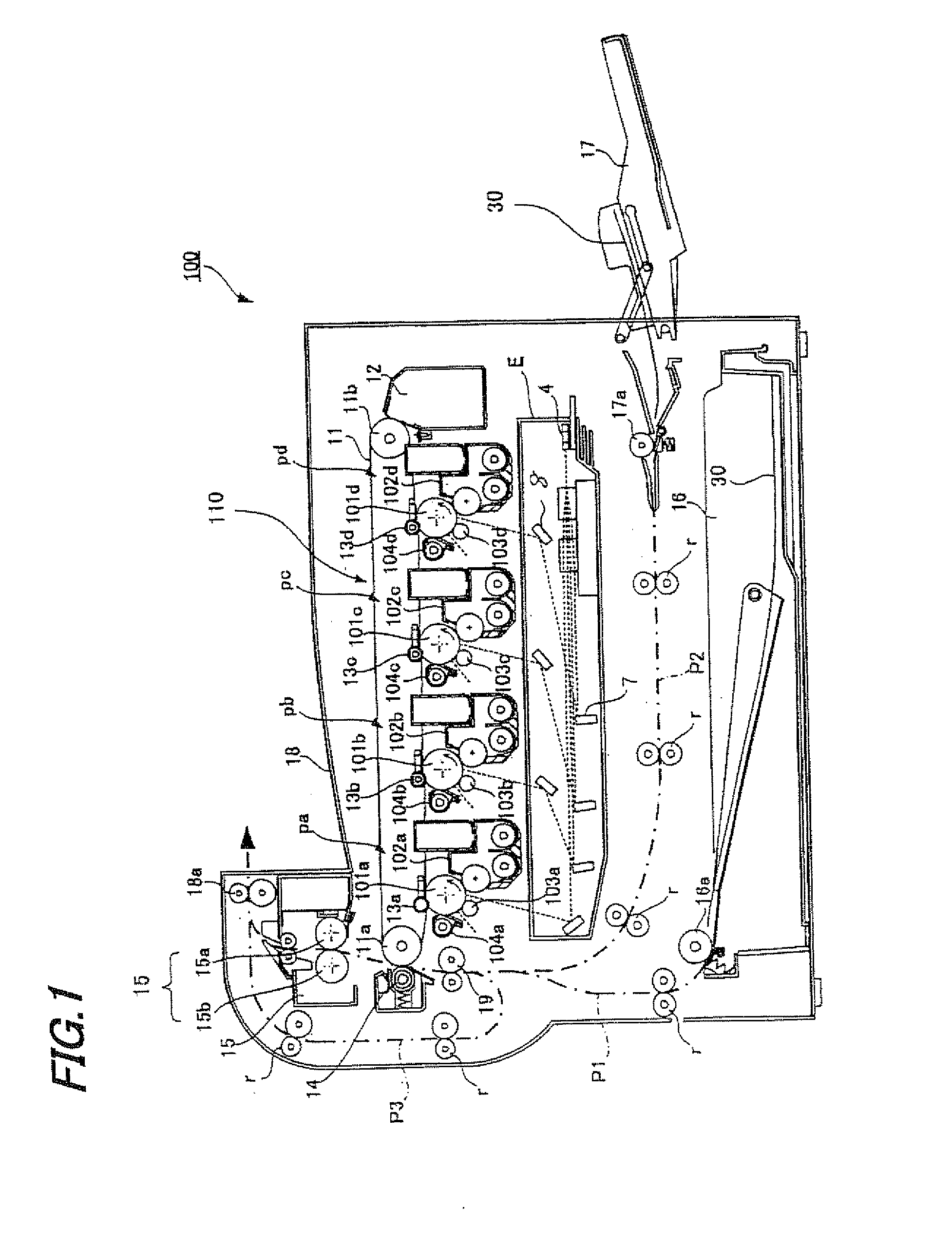
[0047]FIG. 1 is an illustrative view showing the configuration of an image forming apparatus according to the embodiment of the present invention.

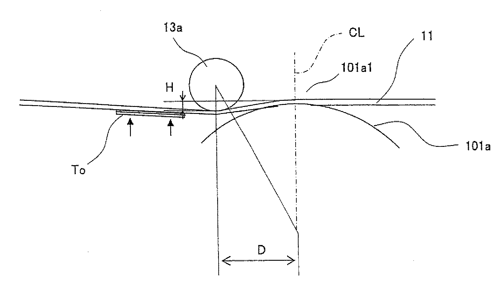
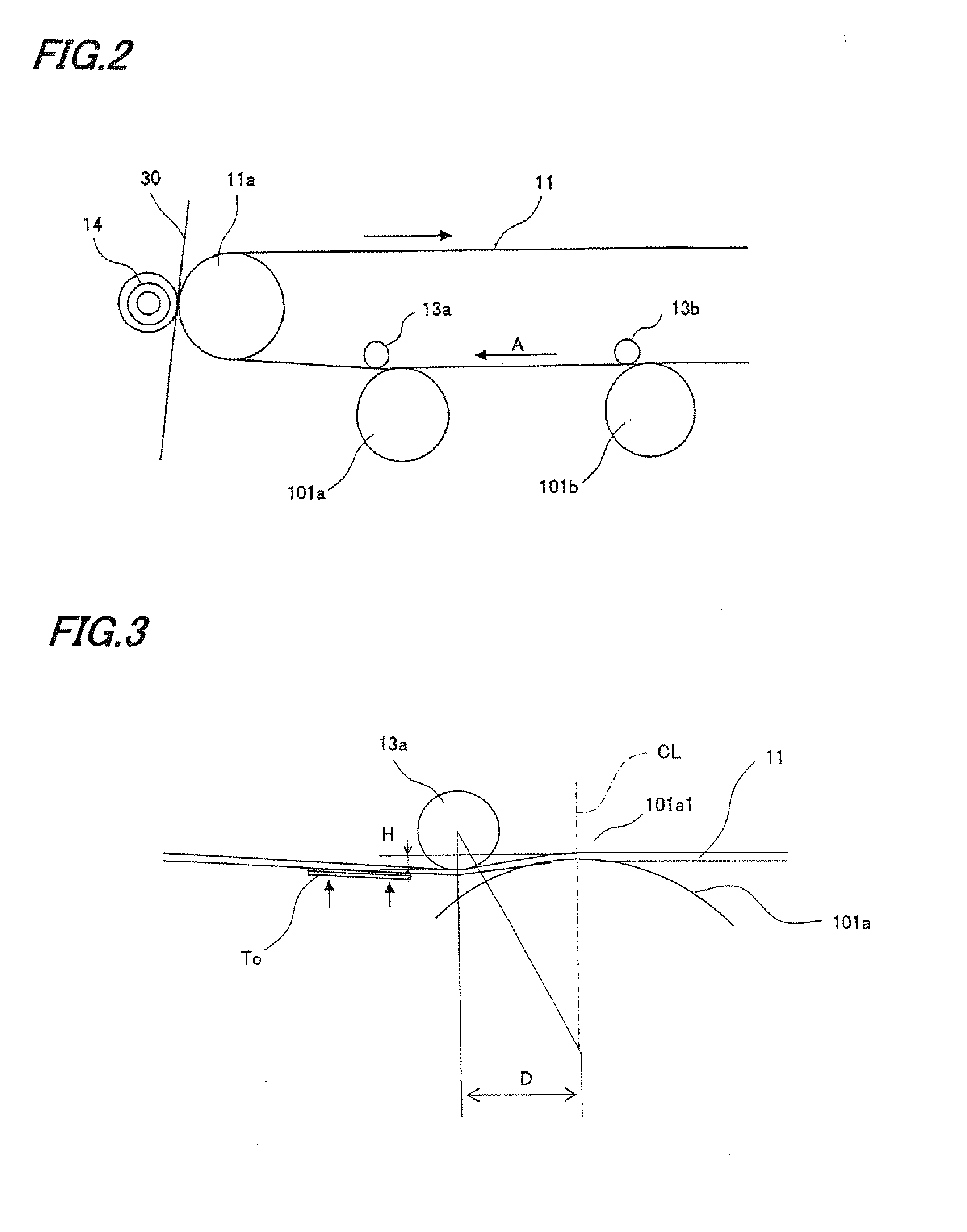
[0048]As shown in FIG. 1, an image forming apparatus 100 of the present embodiment includes a transfer belt unit 110 comprised of an intermediate transfer belt (intermediate transfer medium) 11 for temporarily supporting the toner images formed on photoreceptor drums (photoreceptors) 101 and primary transfer rollers (transfer rollers) 13 for pressing intermediate transfer belt 11 against photoreceptor drums 101, to transfer the toner images formed on the surfaces of photoreceptor drums 101 by moving intermediate transfer belt 11 along the surface of each photoreceptor drum 101.

[0049]To begin with, the whole configuration of image forming apparatus 100 of the present embodiment will be described.

[0050]Image formi...


PUM


Abstract

An image forming apparatus includes a transfer belt unit which has an intermediate transfer belt for supporting toner images and primary transfer rollers for pressing the intermediate transfer belt against corresponding photoreceptor drums and moves the intermediate transfer belt along the surface of each photoreceptor drum to transfer the toner images to the intermediate transfer belt. The intermediate transfer belt is formed so as to be 30 μm to 50 μm in average thickness, each primary transfer roller is arranged at a position, along the moving direction of the intermediate transfer belt, which is deviated downstream with respect to the moving direction from the position where the intermediate transfer belt is in contact with the photoreceptor and which is projected toward the photoreceptor drum side so as to press the intermediate transfer belt against photoreceptor with a nip pressure ranging from 10 gf/cm2 to 40 gf/cm2.

Description

[0001]This Nonprovisional application claims priority under 35U.S.C. §119(a) on Patent Application No. 2007-269234 filed in Japan on 16 Oct. 2007, the entire contents of which are hereby incorporated by reference.BACKGROUND OF THE INVENTION[0002](1) Field of the Invention[0003]The present invention relates to a transfer belt unit that uses a belt-like intermediate transfer medium to perform transfer of the toner image formed on the photoreceptor drum surface by an electrophotographic image forming process as well as relating to an image forming apparatus using the transfer belt unit.[0004](2) Description of the Prior Art[0005]Conventionally, in the field of image forming apparatus for performing an electrophotographic image forming process, there have been known image forming apparatus which adopt a so-called intermediate transfer system in which the toner image formed on the surface of the photoreceptor (photoreceptor drum) is primarily transferred to an intermediate transfer mediu...

Claims


Application Information

Patent Timeline
Patent Type & Authority Applications(United States)
IPC IPC(8): G03G15/20
CPCG03G2215/0132G03G15/1605
Inventor HIRAI, MASASHIKAKUI, MIKIOMASUDA, YOSHIAKIMURAKAMI, SUSUMUISHIKAWA, KAZUAKITANAKA, TOMOMI
Owner SHARP KK
Why Eureka
Try Eureka