Fuel cells

a fuel cell and cell technology, applied in the field of fuel cells, can solve the problems of reducing the power generation capacity of the fuel cell, reducing the power generation capacity, and the reactive gas may not be fully fed over the whole face of the catalyst electrode, and achieve the effect of convenient processing and efficient power generation

Inactive Publication Date: 2009-04-16
TOYOTA JIDOSHA KK
View PDF10 Cites 19 Cited by
  • Summary
  • Abstract
  • Description
  • Claims
  • Application Information

AI Technical Summary

Benefits of technology

[0043]This arrangement effectively equalizes the in-plane distribution of water over the whole surface of at least one of the anode and the cathode of the cell laminate and ensures the two-dimensionally distributed supply of the water, thus attaining efficient power generation.
[0044]In the fuel cell stack of any of the above arrangements, the anode-facing plate, the cathode-facing plate, and the middle plate are preferably all flat plate members. The use of the flat plate members desirably facilitates processing of the anode-facing plate, the cathode-facing plate, and the middle plate.
[0045]In the fuel cell stack according to this aspect of the invention, the multiple water inlets may be provided in the anode-facing plate. This arrangement enables the electrolyte membrane to be kept moist in the thickness direction.

Problems solved by technology

In some operating conditions, however, the produced water is locally accumulated on the surface of the anode or on the surface of the cathode and partly blocks the fuel gas (hydrogen) passage or the oxidizing gas (oxygen) passage.
Such blocking of the gas passage undesirably interferes with the homogeneous supply of the fuel gas or the oxidizing gas over the whole surface of the anode or the whole surface of the cathode and may decrease the power generation capacity of the fuel cells.
The problem of the decreasing power generation capacity is not uniquely caused by the local accumulation of the produced water but is also induced by local accumulation of unreacted gas components unused for the electrochemical reaction of power generation (for example, nitrogen included in the oxygen-containing air used as the oxidizing gas) on the surface of the anode or on the surface of the cathode.
In the case of supply of the humidified reactive gases from the specific parts of the peripheries of the catalyst electrodes (the anode and the cathode) in the fuel cells, the reactive gases may not be fully fed over the whole faces of the catalyst electrodes.
This leads to insufficient humidification in some part of the electrolyte membrane.
The insufficient humidification may cause the electrolyte membrane to be locally dried and deteriorate the cell performance of the fuel cells.

Method used


Image

  • Fuel cells
  • Fuel cells
  • Fuel cells

Examples


first embodiment

A. First Embodiment

A1. Structure of Fuel Cell System

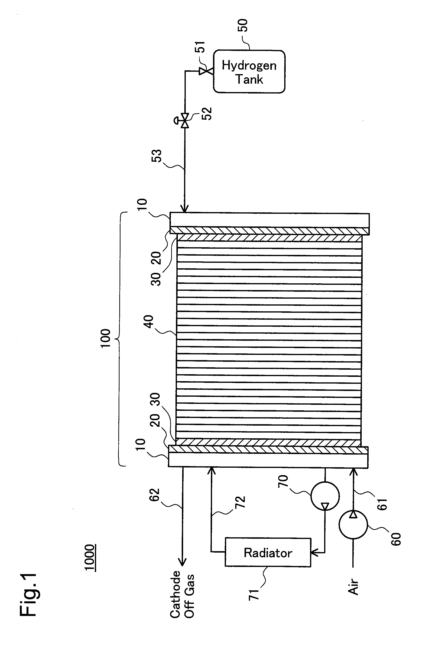
[0076]FIG. 1 schematically illustrates the structure of a fuel cell system 1000 including a stack of fuel cells or fuel cell stack 100 in a first embodiment of the invention.

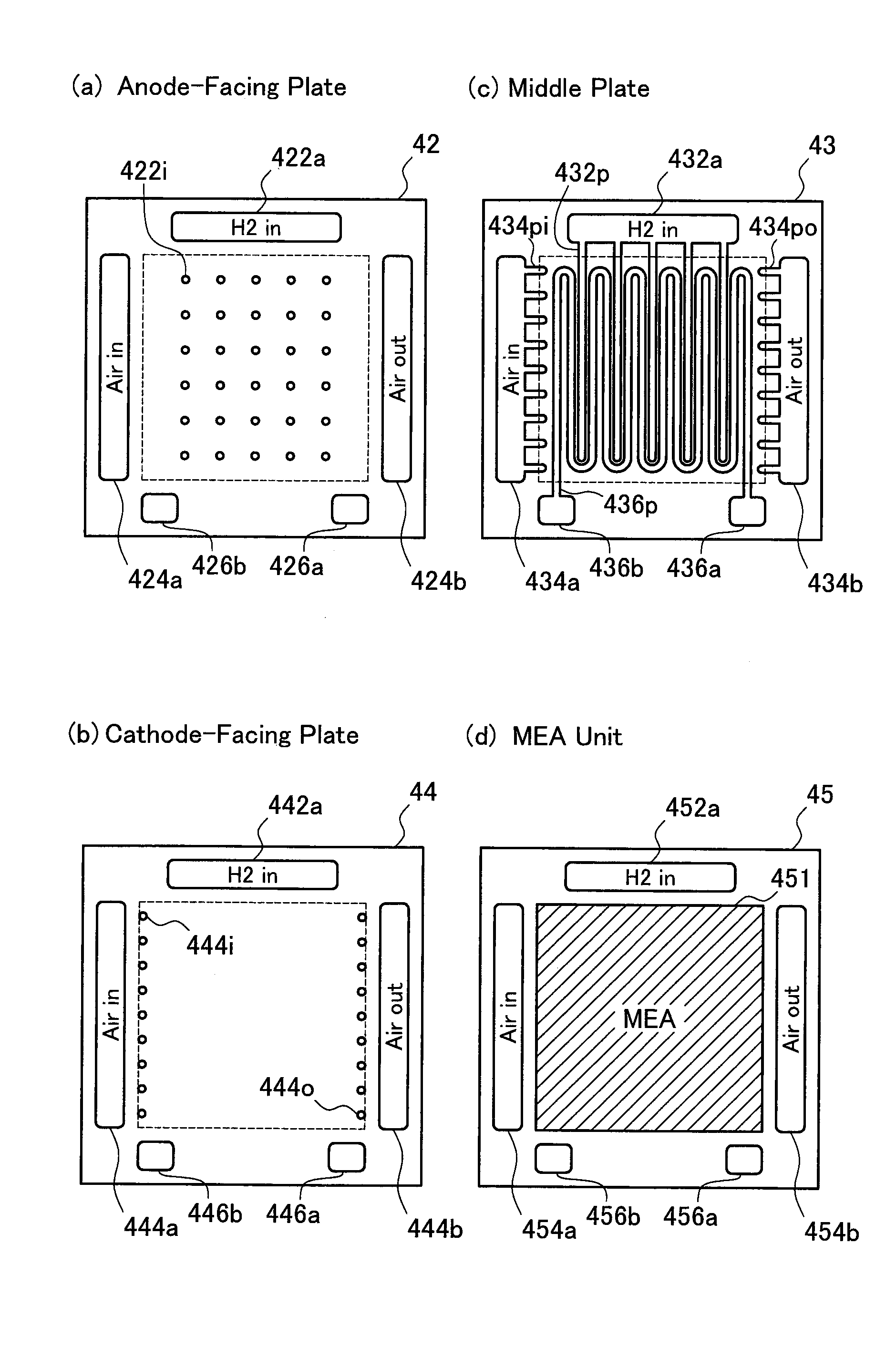
[0077]The fuel cell stack 100 has a stack structure of multiple cell laminates stacked via separators. Each cell laminate generates electricity through electrochemical reaction of hydrogen with oxygen and has an anode and a cathode arranged across a proton-conductive electrolyte membrane as explained later. A solid polymer membrane is adopted for the electrolyte membrane in this embodiment. The separator of this embodiment consists of three flat metal plates that are stacked and joined together and respectively have multiple through holes. The three metal plates of the separator form a flow path of hydrogen as a fuel gas to be supplied to the anode, a flow path of the air as an oxidizing gas to be supplied to the cathode, and a flow path of cooling water. The n...

second embodiment

B. Second Embodiment

[0104]A fuel cell system of a second embodiment has a similar structure to that of the fuel cell system 1000 of the first embodiment, except a fuel cell stack that is different from the fuel cell stack 100 of the first embodiment. The following description thus regards the structure of the fuel cell stack in the second embodiment.

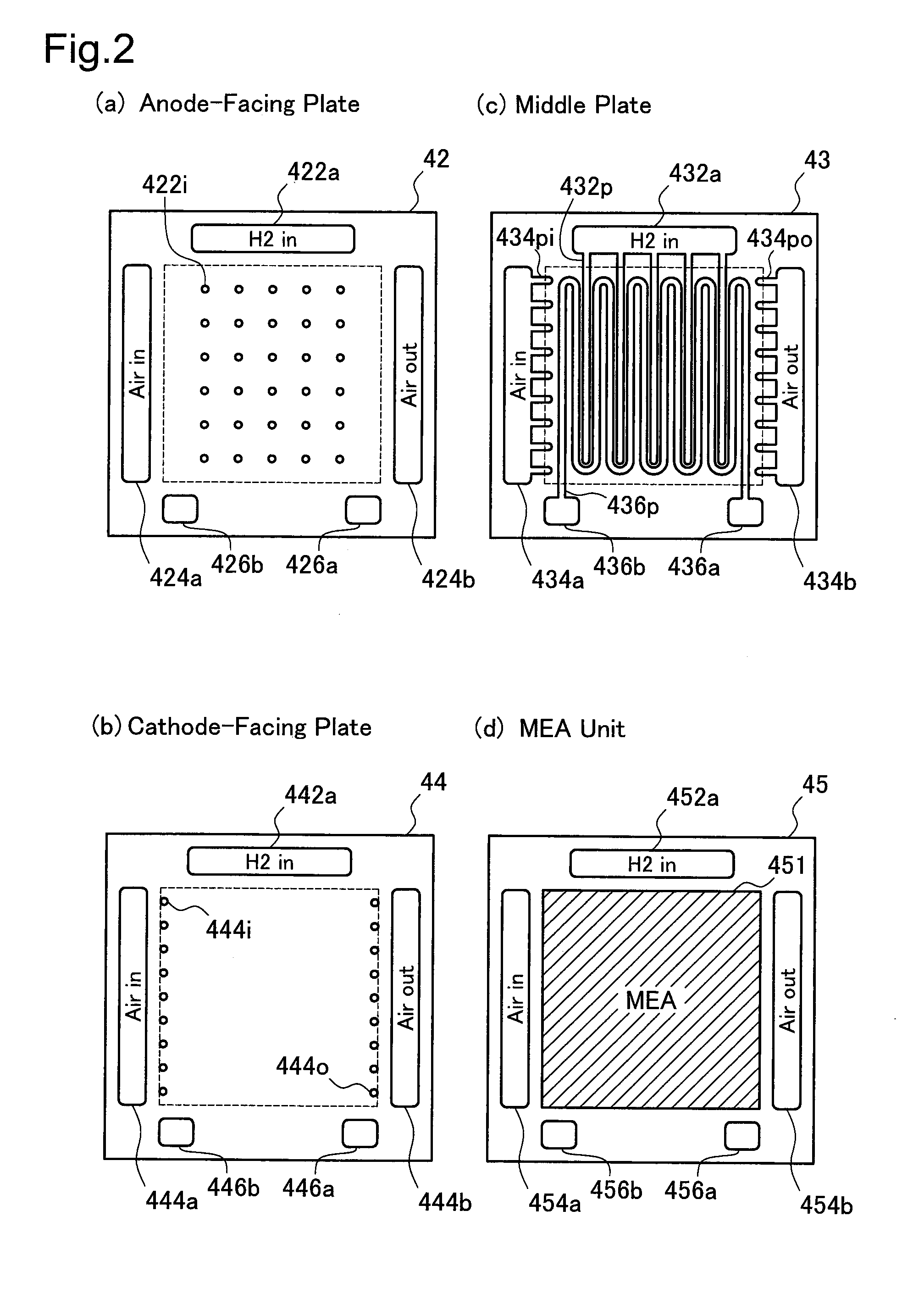
[0105]FIG. 6 is plan views showing constituents of a fuel cell module 40A in the fuel cell stack of the second embodiment. Like the fuel cell module 40 of the first embodiment, the fuel cell module 40A of the second embodiment is constructed by stacking a separator 41A and an MEA unit 45A. The separator 41A is obtained by stacking an anode-facing plate 42A, a middle plate 43A, and a cathode-facing plate 44A in this sequence and hot pressing the laminate of these three plates. In the structure of this embodiment, the anode-facing plate 42A, the middle plate 43A, and the cathode-facing plate 44A are stainless steel plates of an identical r...

third embodiment

C. Third Embodiment

[0118]FIG. 9 schematically illustrates the structure of a fuel cell system 1000B including a fuel cell stack 100B in a third embodiment. Unlike the fuel cell system 1000 of the first embodiment, the fuel cell system 1000B of the third embodiment includes an exhaust pipe 56 to discharge the anode off gas out of the fuel cell stack 100B and a circulation pipe 54 to recirculate the anode off gas to a pipe 53 for hydrogen supply. The exhaust pipe 56 is equipped with an exhaust valve 57, and the circulation pipe 54 is equipped with a pump 55. The fuel cell stack 100B also has a structure of discharging the anode off gas as explained later. Controlling the operations of the pump 55 and the exhaust valve 57 switches over the flow of the anode off gas between discharge out of the fuel cell stack 100B and recirculation to the pipe 53. The other structural elements of the fuel cell system 1000B of the third embodiment are identical with those of the fuel cell system 1000 of...


PUM

PropertyMeasurementUnit
thicknessaaaaaaaaaa
specific areaaaaaaaaaaa
areaaaaaaaaaaa

Abstract

In a fuel cell stack, each separator is constructed by sequentially stacking and joining an anode-facing plate 42, a middle plate 43, and a cathode-facing plate 44. The anode-facing plate 42 has multiple hydrogen inlets 422i arranged in a two-dimensionally distributed manner on its plate surface. This arrangement effectively prevents a decrease of power generation capacity due to local accumulation of water produced in the course of electrochemical reaction for power generation or other impurities on the surface of either an anode or a cathode.

Description

TECHNICAL FIELD[0001]The present invention relates to fuel cells and more specifically to fuel cells having a stack structure of multiple cell laminates stacked via separators, where each cell laminate has an anode and a cathode formed on the opposed faces of a proton-conductive electrolyte membrane.BACKGROUND ART[0002]Fuel cells generating electric power through electrochemical reaction of hydrogen with oxygen have been noted as an efficient energy source. As disclosed in Japanese Patent Laid-Open No. 2003-68318, one typical arrangement of such fuel cells is a stack structure where membrane electrode assemblies and separators are alternately arranged and each membrane electrode assembly has an anode (hydrogen electrode) and a cathode (oxygen electrode) formed on opposed faces of a proton-conductive electrolyte membrane (the fuel cells of the stack structure are referred to as ‘fuel cell stack’).[0003]Various techniques have been proposed for the structure of the separator adopted i...

Claims


Application Information

Patent Timeline
Patent Type & Authority Applications(United States)
IPC IPC(8): H01M8/02
CPCH01M8/0228H01M8/0247Y02E60/50H01M8/0263H01M8/0267H01M8/0258H01M8/2457H01M8/2483H01M8/02H01M8/24H01M8/2459
Inventor SHIBATA, KAZUNORIOGAWA, TOMOHIRO
Owner TOYOTA JIDOSHA KK
Why Eureka
Try Eureka