Wind Power Generation System

a wind power generation system and wind power technology, applied in the direction of electric generator control, dynamo-electric converter control, machines/engines, etc., can solve the problems of iron loss, copper loss, etc., to reduce the loss of power conversion device switching, high-efficiency wind power generation system, the effect of reducing the loss of power conversion devi

Inactive Publication Date: 2008-06-19
HITACHI LTD
View PDF8 Cites 36 Cited by
  • Summary
  • Abstract
  • Description
  • Claims
  • Application Information

AI Technical Summary

Benefits of technology

[0008]With the system, since a control paused period is set for each phase in the PWM control, the switching loss for the power conversion device is reduced, thereby realizing a highly efficient wind power generation system. At this time, the control paused period for one phase overlaps the control period for another phase, and the pulse density of the inter-phase voltage is low. Also, the control period for one phase overlaps the control period for another phase, and the pulse density of the inter-phase voltage is low. Therefore, a changing pulse density features the PWM pulse...

Problems solved by technology

Especially, there is the problem of a switching loss with an IGBT (insulated gate bipolar transistor) etc. for use in a pow...

Method used


Image

  • Wind Power Generation System
  • Wind Power Generation System
  • Wind Power Generation System

Examples


first embodiment

[0024]The configuration of the wind power generation system according to the first embodiment of the present invention is described below with reference to the attached drawings.

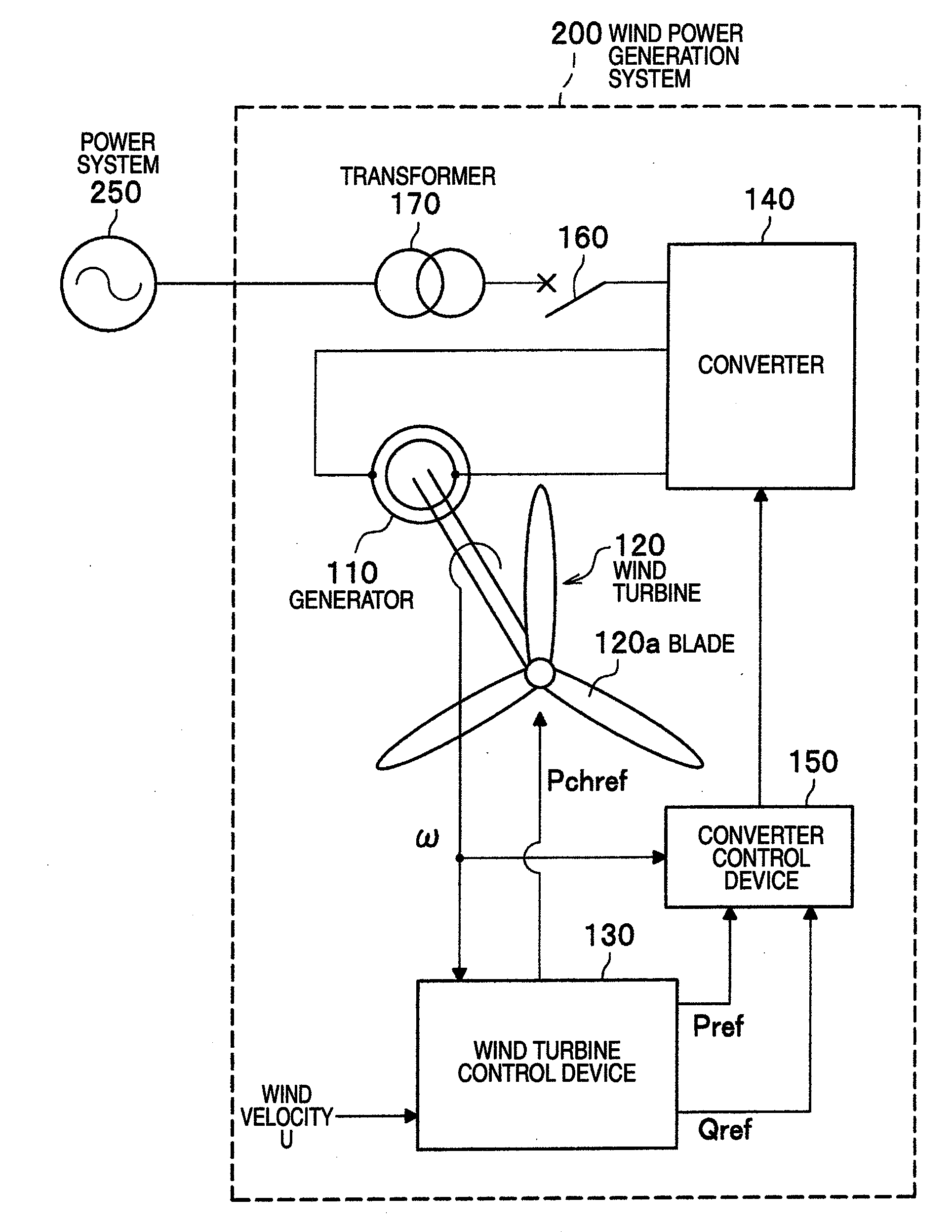
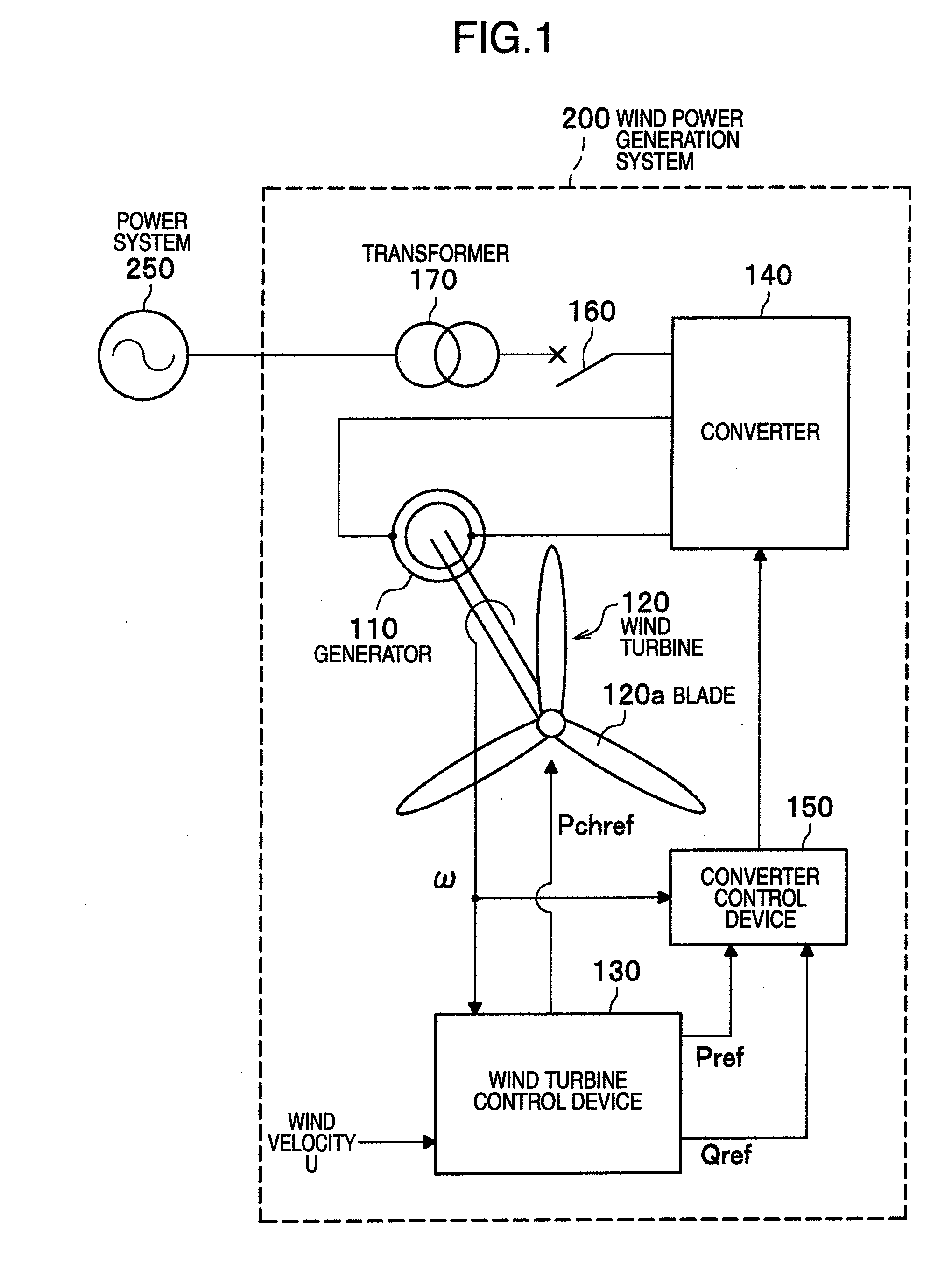
[0025]In FIG. 1, a wind power generation system 200 is connected to a power system 250, and is provided with a converter (excitation device) 140 as a power conversion device, a generator 110, a wind turbine 120, a wind turbine control device 130, a converter control device 150, a transformer 170, and a breaker 160. The power system 250 can be regarded simply as a power supply when it has a large capacity, and transmits power to user home, a factory, etc. through power lines not shown in the attached drawings.

[0026]The wind turbine 120 is provided with three blades 120a, and is mechanically connected to a rotor of the generator 110, and the generator 110 is electrically connected to the converter 140. As necessary, the wind turbine 120 is connected to a rotor through a gear. The breaker 160 has the function o...

second embodiment

[0088]Next, the second embodiment is described below with reference to FIGS. 9A to 9D, FIG. 10 and FIG. 11. The present embodiment is different from the first embodiment in generating the voltage commands Vun, Vvn, Vwn. The similar functions to those in the first embodiment are assigned the same reference numerals, and the explanation is omitted here.

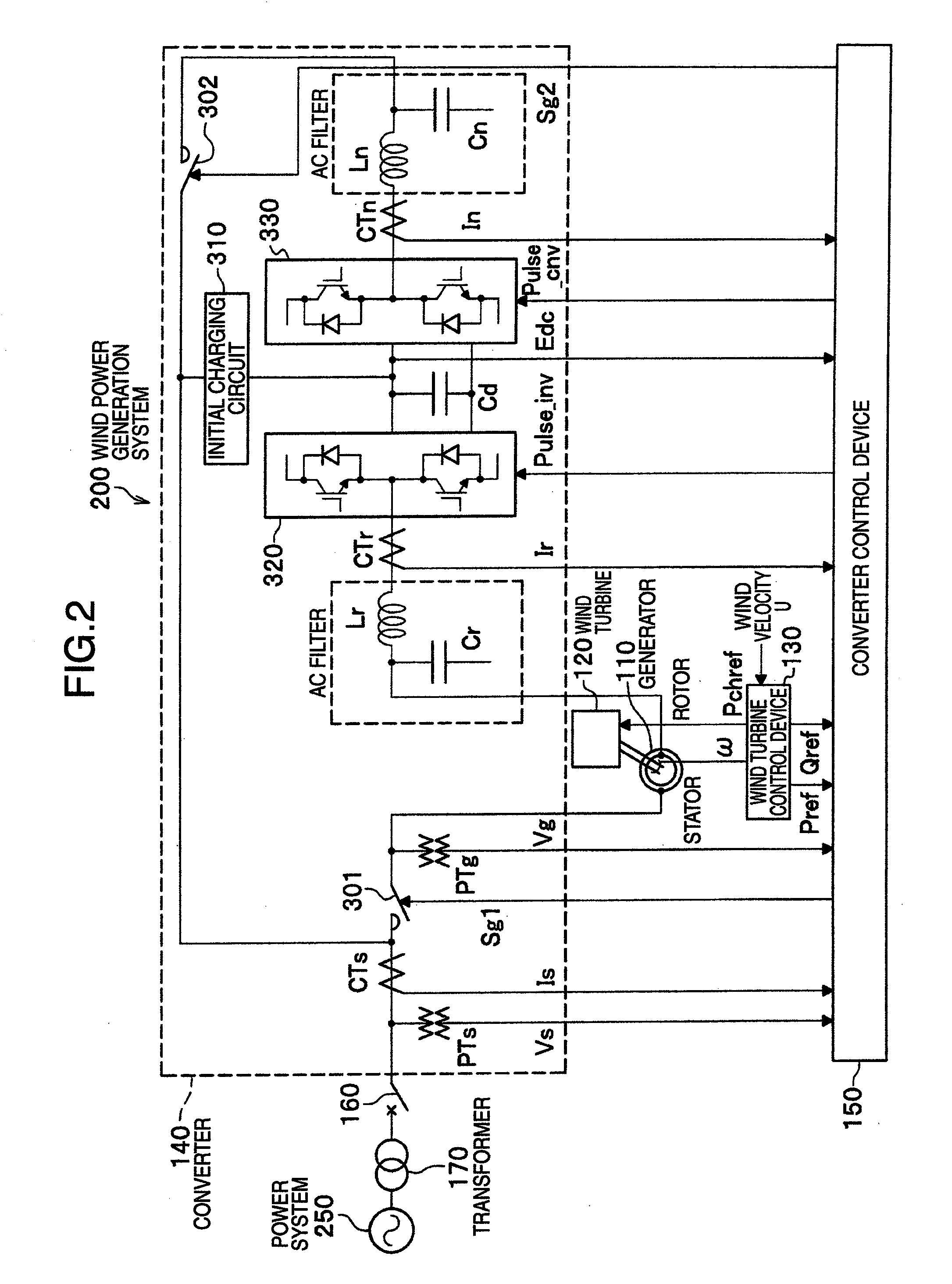
[0089]As described above with reference to FIG. 3, the pulse for issuing an ON / OFF command input to the upper element and the lower element of the IGBT element configuring the power conversion device according to the pulse signal generated by the PWM calculating unit inputs Pulse_cnv_u, Pulse_cnv_v, and Pulse_cnv_w to the upper element, and the inverted pulses Pulse_cnv_un, Pulse_cnv_vn, and Pulse_cnv_wn to the lower element. The subscript n of the pulse signal indicates an inverse signal, that is, the ON / OFF pulse of the lower element.

[0090]In the pulse signal of the same phase, when the upper pulse and the lower pulse are simultaneous...

third embodiment

[0094]Although a wound-rotor induction generator (secondary excitation generator) is used for the 110 in each of the embodiments described above, a permanent magnetic generator (other synchronous generators are acceptable) can also be used.

[0095]In FIG. 12, the wind power generation system 210 includes a generator 115, a wind turbine 120, a power command generation device 135, converters 320 and 330, a converter control device 155, a transformer 170, a breaker 160, a capacitor Cd, capacitors Cr and Cn, reactors Lr and Ln, an electromagnetic contactor 302, voltage sensor PTs and PTg, and current sensors CTr and CTn, and the components are connected to the power system 250.

[0096]The power command generation device 135 generates the power commands Pref and Qref from the wind velocity U. The converter control device 155 calculates the active power Ps and the reactive power Qs from the generator voltage Vr and the generator current Ir, and controls the converter 320 on the generator side...


PUM


Abstract

A wind power generation system includes: a wind turbine in which at least one blade is mounted on an axis; a generator for generating multiphase alternating current power by rotation of the axis; and a multiphase power conversion device for performing PWM-control for adjustment and output of generated power of the generator. With the configuration, the PWM-control provides for each phase a control paused period in which no overlap occurs. Thus, the pulse density between the control period and the control paused period of other phases is low, thereby generating high and low density in an inter-phase pulse.

Description

CROSS-REFERENCE TO RELATED APPLICATION[0001]The present application relates to subject matters described in a co-pending patent application Ser. No. 11 / 769,753 filed on Jun. 28, 2007 entitled “VARIABLE SPEED WIND POWER GENERATION SYSTEM” and Ser. No. 11 / 751,742 filed on May 22, 2007 entitled “WIND POWER GENERATION APPARATUS, WIND POWER GENERATION SYSTEM AND POWER SYSTEM CONTROL APPARATUS” both by Masaya Ichinose, et al. and assigned to the assignees of the present application. The disclosures of these co-pending applications are incorporated herein by reference.BACKGROUND OF THE INVENTION[0002]The present invention relates to a wind power generation system provided with a generator and a multi-phase power conversion device for PWM control.[0003]A wind power generation system is provided with a blade that converts wind power energy into rotational energy, a generator for acquiring electric power from the rotational energy transmitted to a rotor, and a power conversion device for outp...

Claims


Application Information

Patent Timeline
IPC IPC(8): H02P9/04F03D9/00
CPCF03D9/003F05B2220/70642H02P2101/15H02P21/0035Y02E10/725H02P9/007H02P21/22F03D9/255Y02E10/72F03D7/028
Inventor ICHINOSE, MASAYAOOHARA, SHINYAFUTAMI, MOTOOMATSUTAKE, MITSUGU
Owner HITACHI LTD
Why Eureka
Try Eureka