Method for saving energy through injection air suction in thermodynamic process

A thermal process and thermal energy technology, applied in jet pumps, separation methods, jet propulsion devices, etc., can solve the problems of restricting extensive development, difficult to increase pressure parameters, poor investment cost and efficiency, etc., to simplify the jet device and shorten the jet length. , the effect of avoiding throttling loss

Active Publication Date: 2012-11-28
张玉良
View PDF10 Cites 33 Cited by
  • Summary
  • Abstract
  • Description
  • Claims
  • Application Information

AI Technical Summary

Problems solved by technology

[0004] In addition, micro-grid distributed power generation is of great significance in terms of power security, renewable energy utilization, and users' adoption of cogeneration of heat, power and cooling to achieve high efficiency and energy saving. Parameters, especially pressure parameters are difficult to go up
Patent application CN200810182738.9 proposes a thermodynamic booster thermodynamic cycle method, which is an effective solution for small steam units to achieve high-parameter steam, but it is difficult to have corresponding high-parameter model

Method used


Image

  • Method for saving energy through injection air suction in thermodynamic process
  • Method for saving energy through injection air suction in thermodynamic process
  • Method for saving energy through injection air suction in thermodynamic process

Examples


Embodiment 1

[0054] Embodiment 1, structure and principle of composite jet pumping:

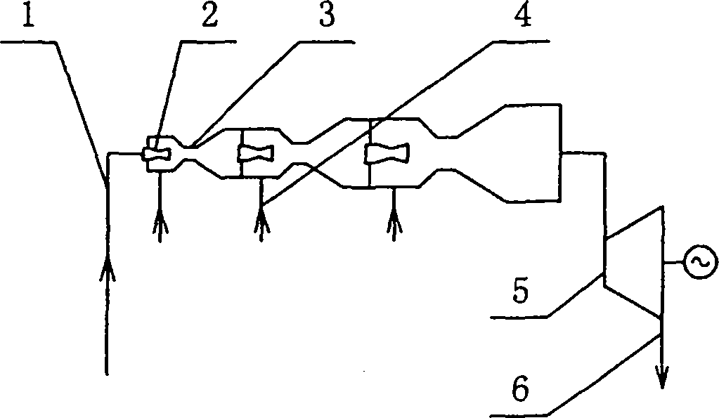
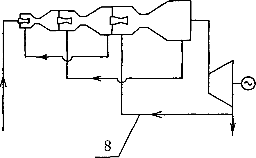
[0055] as attached figure 1 In the three-stage series structure of the jet extractor shown, the high-parameter power source enters the main air inlet of the extractor through the pipeline 1, and after spraying through the nozzle 2, the low-parameter gas source is drawn into the low-parameter gas source through the suction pipeline 4, and then passes through the throat 3 Together enter the deceleration diffuser chamber to complete the first-stage pumping, then enter the second-stage and third-stage pumping process, and finally enter the turbogenerator set 5 to expand and perform work, and then discharge the exhaust gas through the pipeline 6. The arrow in the figure indicates the direction of the air flow. attached figure 2 It is a three-stage series series and adopts a circular jet pumping structure. Each stage extracts the gas source after the mixed and diffused air of the lower stage, and the final st...

Embodiment 2

[0058] Embodiment 2, heat blower:

[0059] as attached Figure 7 The multi-stage cycle compound jet extractor shown is generally used for vacuum extraction, and can also be used for thermal induction or thermal blast when the power source is air or flue gas, especially for large fans, which avoids the need for electric power. Process and wind wheel efficiency loss, can fully play the role of energy saving.

Embodiment 3

[0060] Embodiment 3, jet pumping water source heat pump:

[0061] as attached Figure 8 In the water source heat pump or refrigeration system shown, the composite jet pumping system using hot compressed air as the power source extracts the steam in the raw water tank 17 and then mixes and compresses the steam to condense the heat and increase the temperature. After providing heat for the heat user, the steam in the airflow Further condensed water enters the condensed water tank 19 through air-water separation, air is discharged, and the condensed water is collected and reused. In the raw water tank during operation, a large flow rate is generally required to maintain a stable temperature and liquid level. After the raw water is discharged from the water tank, it can be used for direct cooling or by adding heat exchanger 18 for indirect cooling.


PUM


Abstract

The invention discloses a method for saving energy through injection air suction in a thermodynamic process, which belongs to the field of heat energy power. In order to improve thermal efficiency, a high-parameter power air source is utilized; a composite injection system is formed by an injection air suction thermodynamic system in a circulating air suction mode or by a multistage injection air suction device on the level of more than one in a serial connection, parallel connection and circulation combined mode; and by combining an injection air suction system with a gas turbine engine and other heat and power conversion equipment, a high-parameter air source enters the injection air suction system and then enters the gas turbine engine to do work so as to operate at high efficiency. In addition, an injection refrigeration scheme capable of reducing throttling losses is provided; and the energy saving method can be popularized to wide energy-saving fields of various heat energy and power processes, seawater and other water thermodynamic purification systems and the like, and is high in efficiency and low in cost.

Description

technical field [0001] The invention belongs to the field of thermal power and refrigeration. Background technique [0002] In the field of thermal power, the development of large-capacity and high-parameter units is always pursued in order to pursue high efficiency, but the two parameters of temperature and pressure are always difficult to meet this goal at the same time. Internal combustion engines, gas turbines, and rocket engines have high combustion temperatures but the limited flue gas pressure causes the exhaust gas temperature to be too high during operation. The steam turbine unit of a coal-fired power plant can obtain supercritical pressure, although the temperature and pressure are simultaneously reduced in the steam turbine to reach a low parameter However, the initial parameter of steam temperature is only about 550°C. At present, the thermal efficiency of a single advanced large-scale thermal unit does not exceed 50%, and the thermal efficiency of internal comb...

Claims


Application Information

Patent Timeline
IPC IPC(8): F01D15/10F01D9/02F01K17/02F02C3/32F02C3/34F01K23/02F03B13/00F02K3/06F25B41/06F25B41/00F25B9/08H02K44/08F04F5/22C02F1/06B01D1/14B01D45/16B01D53/24B01D53/00B64C15/14
CPCF04F5/14F04F5/16F04F5/54Y02E20/14
Inventor 张玉良
Owner 张玉良
Why Eureka
Try Eureka