Zoom lens and imaging apparatus incorporating the same

a technology which is applied in the field of zoom lens and imaging apparatus, can solve the problems of increased lens fabrication cost, increased processing difficulty, and increased surface precision of aberration properties, so as to reduce the number of lenses, and improve the effect of chromatic aberration

Active Publication Date: 2009-04-23
OM DIGITAL SOLUTIONS CORP
View PDF5 Cites 12 Cited by
  • Summary
  • Abstract
  • Description
  • Claims
  • Application Information

AI Technical Summary

Benefits of technology

[0084]It is also preferable to have an image transformation block wherein electric signals containing distortion from the zoom lens are transformed into image signals with distortion corrected by image processing. The toleration of the distortion from the zoom lens would work more for a decrease in the number of lenses and its size reductions.
[0085]Furthermore, it is preferable to have an image transformation block wherein image processing is applied to electric signals containing distortion from the zoom lens, thereby implementing distortion correction with a value

Problems solved by technology

Problems with the zoom lenses put forward in Patent Publications 1, 2 and 3 are, however, that as their total lens length gets short at increased zoom ratios, the eff

Method used


Image

  • Zoom lens and imaging apparatus incorporating the same
  • Zoom lens and imaging apparatus incorporating the same
  • Zoom lens and imaging apparatus incorporating the same

Examples


example 1

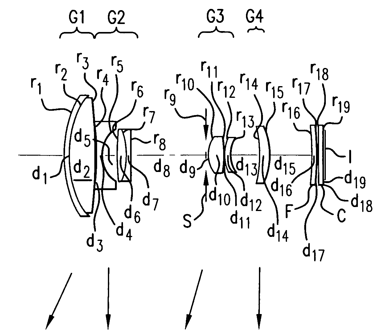
[0117]Example 1 is directed to a zoom lens made up of, in order from its object side, the first lens group G1 of positive refracting power, the second lens group G2 of negative refracting power, the aperture stop S, the third lens group G3 of positive refracting power, the fourth lens group G4 of positive refracting power and the fifth lens group G5 of negative refracting power, as shown in FIG. 1.

[0118]Upon zooming from the wide-angle end to the telephoto end, the respective lens groups move as follows. Throughout Examples 1 to 10, the intermediate state is defined as the point of change in the direction of movement of the second lens group G2, the third lens group G3 or the fourth lens group G4 from the wide-angle end to the telephoto end.

[0119]The first lens group G1 moves toward the object side from the wide-angle end to the telephoto end.

[0120]From the wide-angle end to the intermediate state, the second lens group G2 moves toward the object side while the spacing between the f...

example 2

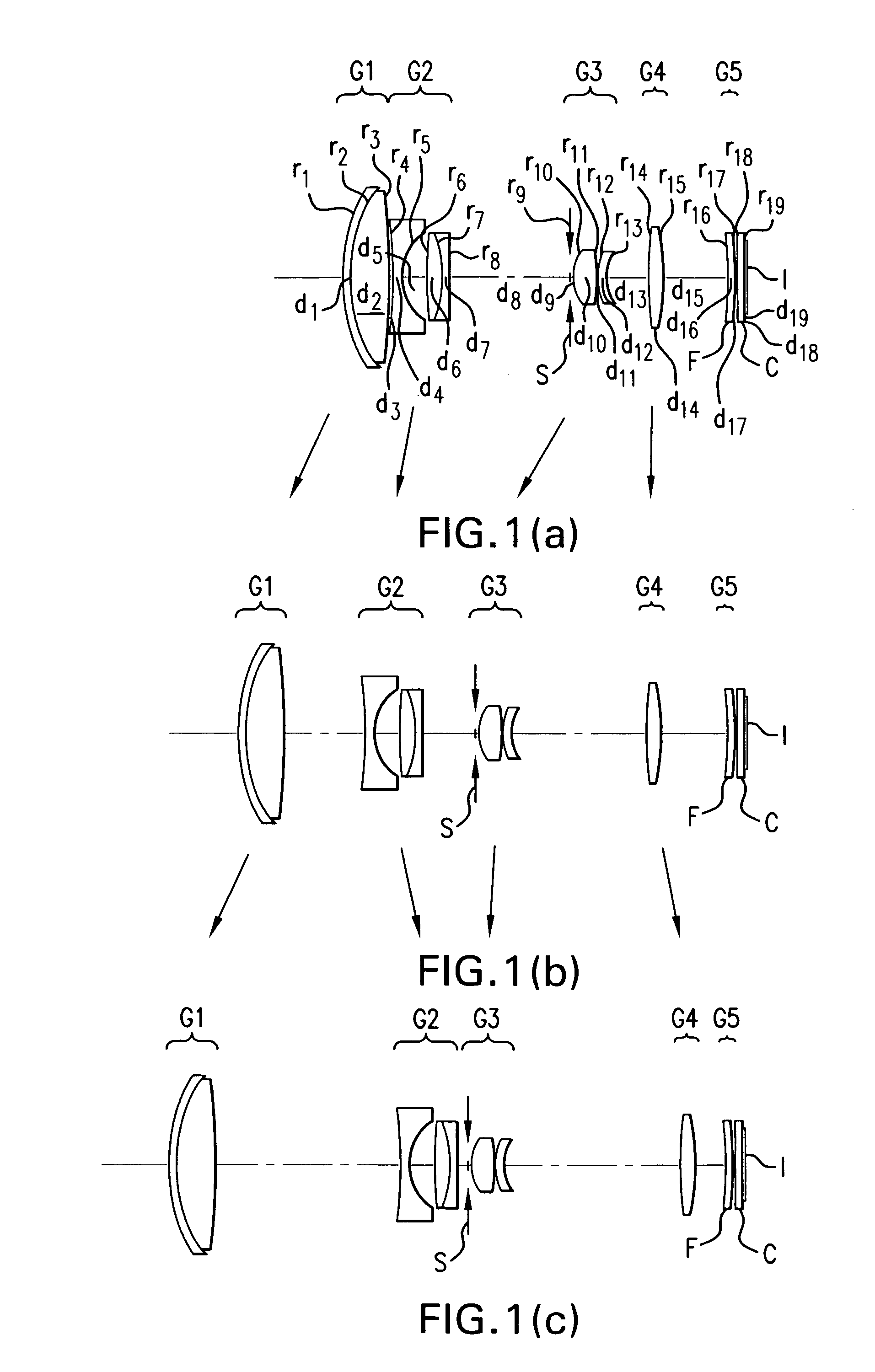
[0125]Example 2 is directed to a zoom lens made up of, in order from its object side, the first lens group G1 of positive refracting power, the second lens group G2 of negative refracting power, the aperture stop S, the third lens group G3 of positive refracting power and the fourth lens group G4, as shown in FIG. 2.

[0126]The first lens group G1 moves toward the object side from the wide-angle end to the telephoto end.

[0127]From the wide-angle end to the intermediate state, the second lens group G2 moves toward the object side while the spacing between the first lens group G1 and it grows wide and the spacing between it and the third lens group G3 becomes narrow and, from the intermediate state to the telephoto end, the second lens group G2 moves toward the image side while the spacing between the first lens group G1 and it grows wide and the spacing between it and the third lens group G3 becomes narrow. In the intermediate state, the second lens group G2 is positioned a little more...

example 3

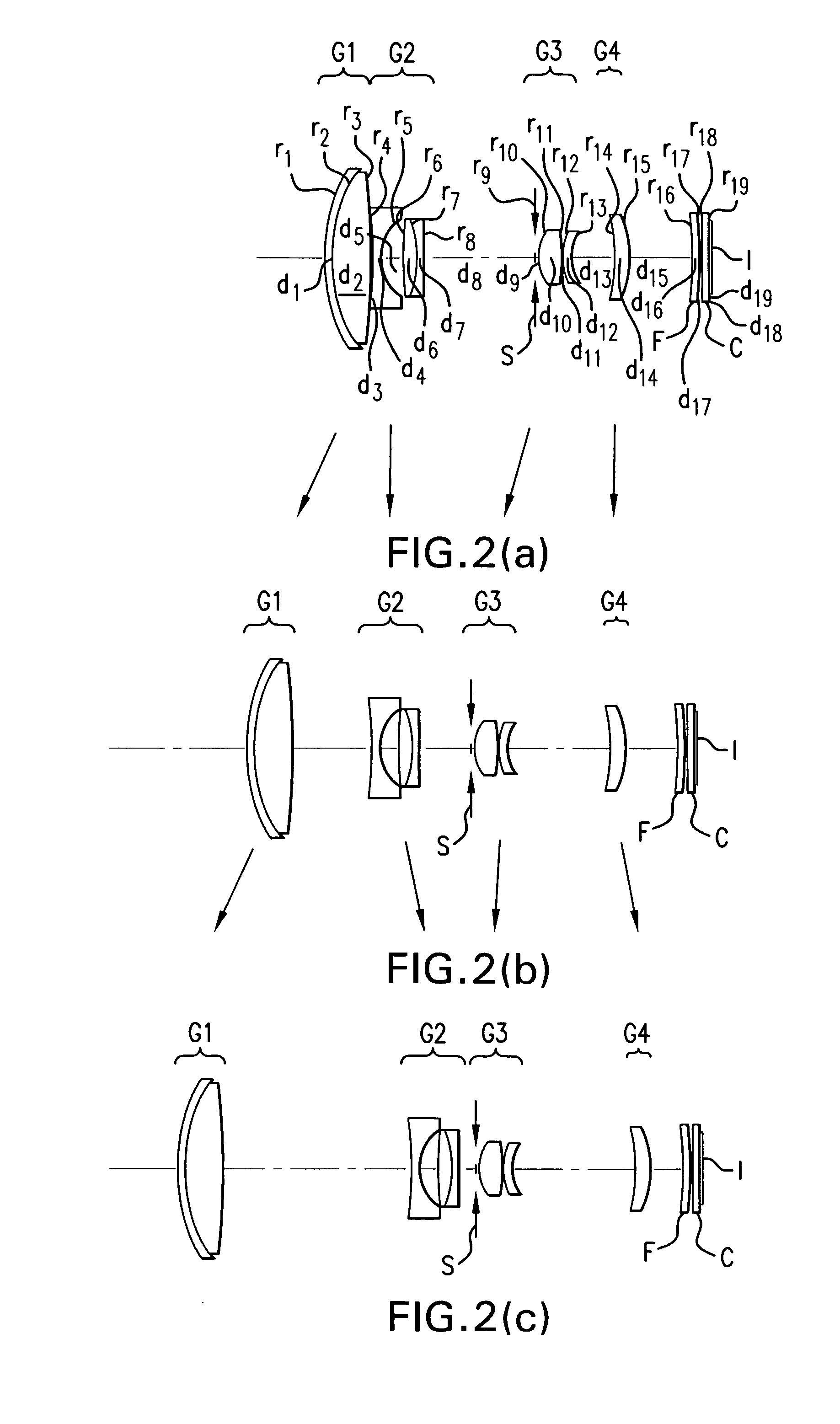
[0132]Example 3 is directed to a zoom lens made up of, in order from its object side, the first lens group G1 of positive refracting power, the second lens group G2 of negative refracting power, the aperture stop S, the third lens group G3 of positive refracting power and the fourth lens group G4, as shown in FIG. 3.

[0133]Upon zooming from the wide-angle end to the telephoto end, the respective lens groups move as follows.

[0134]The first lens group G1 moves toward the object side from the wide-angle end to the telephoto end.

[0135]From the wide-angle end to the intermediate state, the second lens group G2 moves toward the object side while the spacing between the first lens group G1 and it grows wide and the spacing between it and the third lens group G3 becomes narrow and, from the intermediate state to the telephoto end, the second lens group G2 moves toward the image side while the spacing between the first lens group G1 and it grows wide and the spacing between it and the third l...


PUM


Abstract

The invention relates to a zoom lens and an imaging apparatus incorporating the same, and more particularly to a zoom lens of small format that lends itself to imaging apparatus inclusive of video cameras and digital cameras. The zoom lens comprises, in order from its object side, a first lens group G1 of positive refracting power, a second lens group G2 of negative refracting power and a third lens group G3 of positive refracting power. Zooming is implemented by changing the space between the respective lens groups. The first lens group G1 comprises one negative lens and one positive lens in order from the object side. The zoom lens satisfies conditions (1) and (2):
5.0<ft/fw<50.0  (1)
1.4<Nd1p<1.7  (2)
where fw is the focal length of the whole zoom lens system at a wide-angle end, ft is the focal length of the whole zoom lens system at a telephoto end, and Nd1p is the d-line refractive index of the positive lens in the first lens group.

Description

[0001]This application claims benefit of Japanese Application No. 2007-224240 filed in Japan on Aug. 30, 2007, the content of which are incorporated by this reference.BACKGROUND OF THE INVENTION[0002]The present invention relates generally to a zoom lens and an imaging apparatus incorporating the same, and more particularly to a zoom lens of small format that lends itself to imaging apparatus inclusive of video cameras and digital cameras.[0003]In recent years, imaging apparatus such as digital cameras designed to take images of subjects using solid-state imaging devices such as CCDs or CMOSs have became mainstream in place of silver-halide film cameras. Further, they have now a wide spectrum of categories from the commercial high-end type to the compact low-end type.[0004]The present invention gives weight to the compact low-end type category in particular. Users of such low-end type digital cameras would enjoy snapping shots over a wide range of scenes at anytime in anyplace. For ...

Claims


Application Information

Patent Timeline
IPC IPC(8): G02B15/14
CPCG02B15/177G02B15/173G02B15/145113
Inventor WATANEBE, MASAHITOSATORI, TOMOYUKI
Owner OM DIGITAL SOLUTIONS CORP
Why Eureka
Try Eureka