Electronic device

a technology of electronic devices and components, applied in the field of electronic devices, can solve the problems of increasing manufacturing costs

Inactive Publication Date: 2009-04-23
HTC CORP
View PDF19 Cites 113 Cited by
  • Summary
  • Abstract
  • Description
  • Claims
  • Application Information

AI Technical Summary

Benefits of technology

[0010]According to the present invention, an electronic device including a first main body and a second main body is provided. The first main body includes a first housing, a firs magnetic member and a first elastic member. The second main body includes a second housing and a second magnetic member. The second main body is detachably disposed on the first main body. The first elastic member is disposed within the first housing. The first elastic member connecting with the first magnetic member and the first housing makes the first magnetic member floatable within the first housing. When a base surface of the second housing moves close to a surface of the first housing, the second magnetic member and the first magnetic member attract each other so that the first magnetic member moves toward the surface, and thus the magnetic force between the first magnetic member and the second magnetic member is increased so as to hold the relative position of the first and second main bodies.

Problems solved by technology

Because the rotating hinge design or the sliding hinge design has many members, the structure of the electronic device becomes more complicated, hence increasing the manufacturing cost.

Method used


Image

  • Electronic device
  • Electronic device
  • Electronic device

Examples


first embodiment

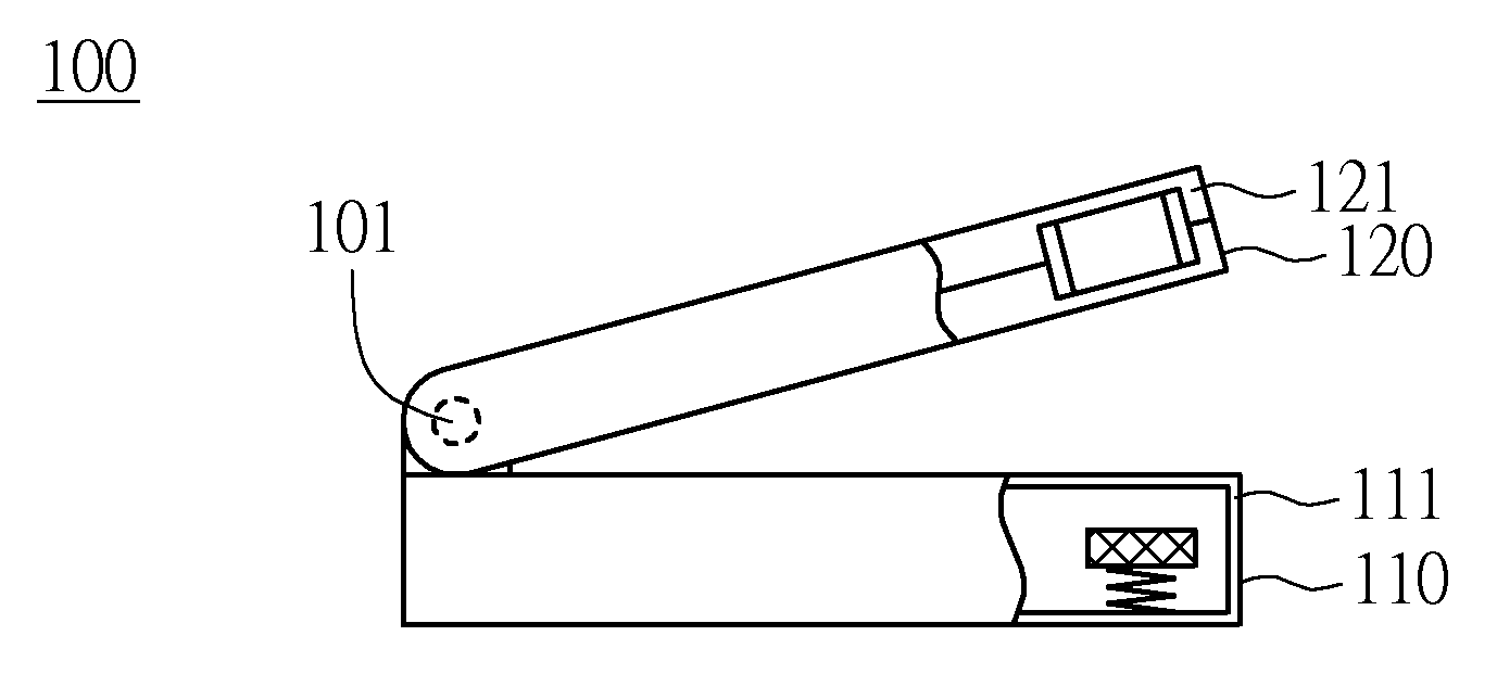
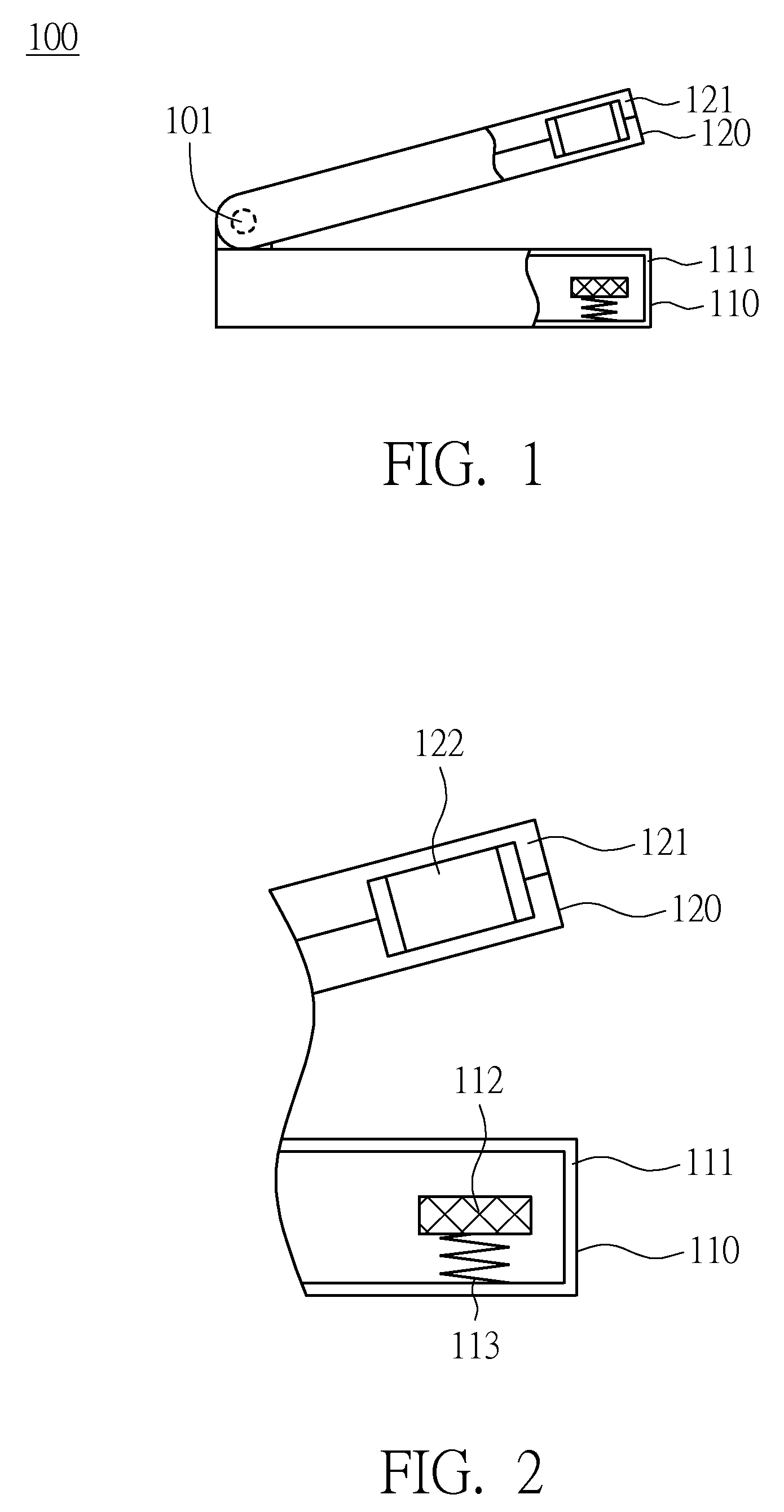
[0034]FIG. 1 is a diagram showing an electronic device 100 according to a first embodiment of the present invention in a non-closed position. FIG. 2 shows a partially enlarged view of the electronic device 100 in FIG. 1 in the non-closed position. The electronic device 100 is, for example, a smart phone, a PDA phone, a laptop computer, an ultra mobile PC (UMPC) or a portable electronic device. As shown in FIG. 1, the electronic device 100 includes a first main body 110 and a second main body 120. The first main body 110 includes a first housing 111, and the second main body 120 includes a second housing 121. The second housing 121 is pivotally connected with the first housing 111. In the present embodiment, the second housing 121 is pivotally connected with the first housing 111 through a pivot 101 so that the second housing 121 is able to rotate relative to the first housing 111. As shown in FIG. 2, the first main body 110 further includes a first magnetic member 112 and a first el...

second embodiment

[0043]FIG. 8 is a diagram showing the electronic device 200 according to a second embodiment of the present invention in a non-closed position. FIG. 9 shows a partially enlarged view of the electronic device 200 in FIG. 8 in the non-closed position. The difference between the present embodiment and the first embodiment is that the second main body 220 further includes a second elastic member 202. As shown in FIG. 8, the electronic device 200 includes a first main body 110 and a second main body 220. The second main body 220 can cover the first main body 110. The first main body 110 includes a first housing 111, and the second main body 220 includes a second housing 203. The second housing 203 is pivotally connected with the first housing 111. The second housing 203 is connected with the first housing 111 through the pivot 201, so that the second housing 203 is able to rotate relative to the first housing 111. In FIG. 9, preferably the first main body 110 further includes a first mag...

third embodiment

[0051]FIG. 15 is a diagram showing an electronic device 300 according to a third embodiment of the present invention having a first main body 310 separated from a second main body 320. The difference between the present embodiment and the first embodiment is that the second main body 320 can be detached from the first main body 310. The first main body 310 includes a first housing 311, a first magnetic member 312 and a first elastic member 313. The first elastic member 313 is disposed within the first housing 311 and connects with the first magnetic member 312 and the first housing 311, so that the first magnetic member 312 is floatable within the first housing 311. The second main body 320 includes a second housing 321 and a second magnetic member 322. The second magnetic member 322 is disposed within the second housing 321. The first magnetic member 312 is, for example a magnet. Preferably, the second magnetic member 322 is made of a magnetic material or is a magnet, for generatin...


PUM


Abstract

An electronic device includes a first main body and a second main body. The first main body includes a first housing, a first magnetic member and a first elastic member. The second main body includes a second housing and a second magnetic member. The second housing is pivotally connected with the first housing. The first elastic member is disposed within the first housing. The first elastic member connecting with the first magnetic member and the first housing makes the first magnetic member floatable within the first housing. The second magnetic member is disposed within the second housing. When the second housing moves close to a surface of the first housing, the magnetic force between the first and second magnetic members is increased, so as to hold the relative position of the first and second main bodies.

Description

[0001]This application claims the benefit of Taiwan application Serial No. 96139740, filed Oct. 23, 2007, the subject matter of which is incorporated herein by reference.BACKGROUND OF THE INVENTION[0002]1. Field of the Invention[0003]The invention relates in general to an electronic device, and more particularly to an electronic device having a weak magnetic force on the surface of its housing.[0004]2. Description of the Related Art[0005]In this era of technology, electronic devices such as portable electronic devices have played an important role in people's lives. For example, laptop computers and mobile phones are compact in size so that users can take notes, process files, surf the internet or check emails anywhere and anytime. As a result, portable electronic devices are very popular in the market now.[0006]Portable electronic device nowadays usually includes a first main body and a second main body. The first main body includes a first housing and an input device, such as a ke...

Claims


Application Information

Patent Timeline
Patent Type & Authority Applications(United States)
IPC IPC(8): H05K7/00
CPCE05B65/006E05C19/16G06F1/1616H05K5/0221G06F1/1677H04M1/0214G06F1/1654G06F1/1679
Inventor SHIH, CHIN-CHUNG
Owner HTC CORP
Why Eureka
Try Eureka