Adjustable Retractor Blade

Inactive Publication Date: 2009-04-23
INVUITY
View PDF6 Cites 83 Cited by
  • Summary
  • Abstract
  • Description
  • Claims
  • Application Information

AI Technical Summary

Benefits of technology

[0007]An adjustable retractor blade may include a vertical blade portion integrated with an adjustable attachment portion, which is used to attach the blade to a support arm or frame. The ad

Problems solved by technology

Frame mounted blades have very limited adjustment capability.
Prior art devices have attempted to provide some position adjustmen

Method used


Image

  • Adjustable Retractor Blade
  • Adjustable Retractor Blade
  • Adjustable Retractor Blade

Examples


Embodiment Construction

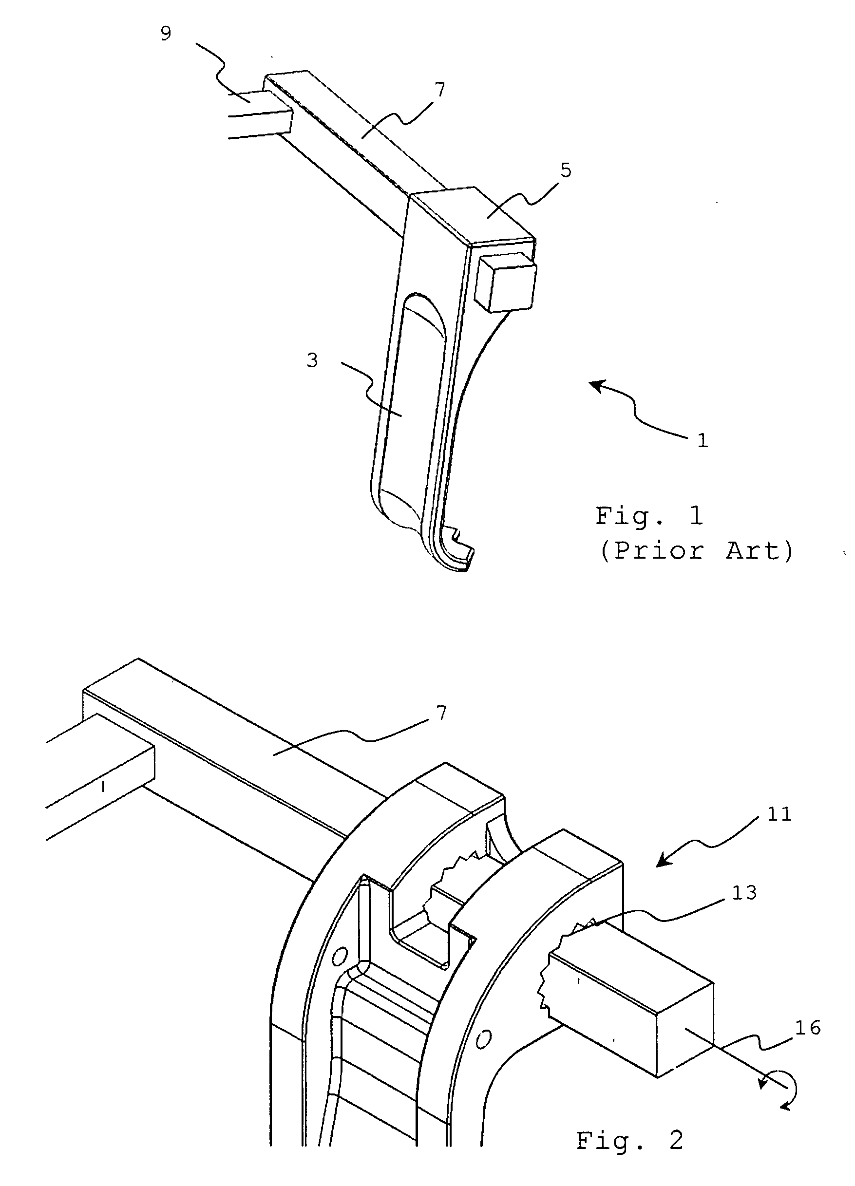
[0027]FIG. 1 shows a prior art retractor blade system 1, which is commonly known as a McCulloch retractor. Vertical blade portion 3 retracts tissue. Attachment portion 5 has a square shaped cutout that engages square arm 7, which is typically integral with a frame 9. The square shaped engagement prevents the retractor blade from rotating about the arm.

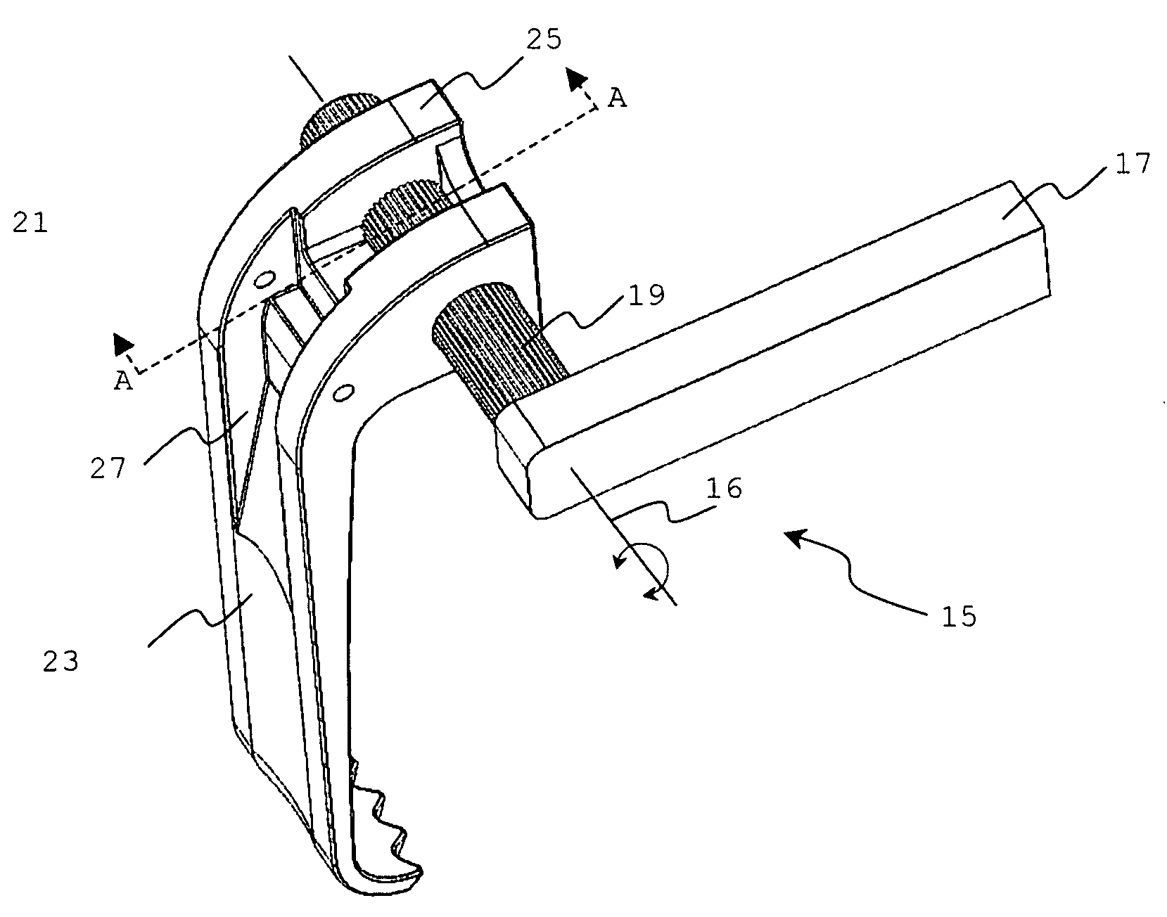
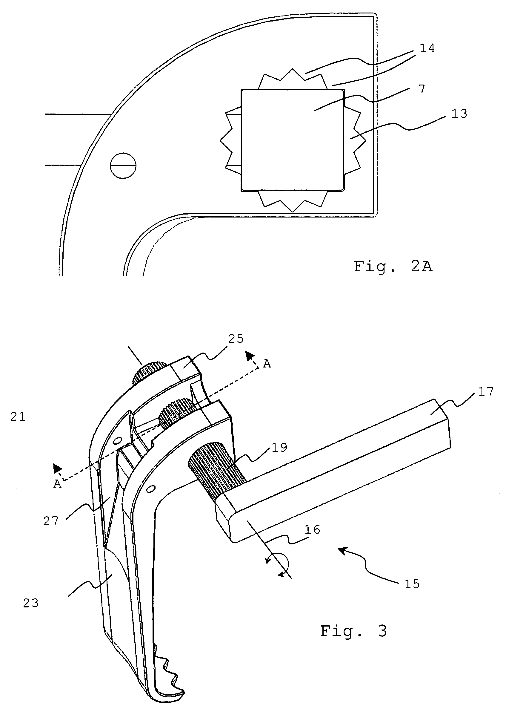
[0028]FIG. 2 illustrates an adjustable blade retractor system 11 that works with the prior art square shaped arm 7. Star shaped engagement channel 13 in the retractor allows for toe-in or radial adjustment of the retractor about first rotational axis 16. The retractor is removed from the arm, the retractor as radially adjusted, toe-in, about the rotation axis, and the retractor is replaced, engaging a different set of teeth 14 in star shaped engagement channel 13.

[0029]FIG. 2a shows a close-up side view of this embodiment showing how arm 7 engages teeth 14 in star shaped engagement channel 13. In this configuration, radial or angular r...


PUM


Abstract

An adjustable retractor blade may include a vertical blade portion integrated with an adjustable attachment portion, which is used to attach the blade to a support arm or frame. The adjustable portion is compatible with existing retractor support arms or frames and allows the vertical blade's position within the body to be easily adjusted without the need for an assistant.

Description

RELATED APPLICATIONS[0001]This application claims priority from copending U.S. provisional patent application 60 / 925,461 filed Apr. 20, 2007.FIELD OF THE INVENTIONS[0002]The inventions described below relate to the field of medical tools and more specifically, to adjustable retractor blades for use in surgery, particularly spine surgery.BACKGROUND OF THE INVENTIONS[0003]Surgical procedures often require the use of retractors to pull apart and hold tissue to expose the underlying tissue on which the surgery is to be performed. Blade retractors are a type of retractor that typically have a flat or slightly curved vertical blade portion that is put into the body. The blade may have a handle portion that is used to manipulate the blade or may be attached to a frame. One or more blade retractors may be used in a surgical procedure. The frame typically allows the blades to be adjusted away from each other to open the surgical wound.[0004]Surgeons often need to adjust the position of the b...

Claims


Application Information

Patent Timeline
IPC IPC(8): A61B1/32
CPCA61B17/0206A61B2017/0256A61B2017/00407
Inventor VAYSER, ALEXGIUNTOLI, DAVID M.GREY, THOMAS L.
Owner INVUITY
Why Eureka
Try Eureka