Method of initiating dtmf diagnostics and other features via a call in diagnostics interface

a technology of diagnostic interface and call in diagnostic interface, which is applied in the direction of digital transmission, data switching networks, instruments, etc., can solve the problems of dtmf interface not allowing the technician to initiate further communication with the central office, and the registration function is disabled

Inactive Publication Date: 2009-04-23
TELLABS VIENNA
View PDF4 Cites 15 Cited by
  • Summary
  • Abstract
  • Description
  • Claims
  • Application Information

AI Technical Summary

Problems solved by technology

After registration is completed, the registration function is disabled and the conventional DTMF interface does not permit the technician to initiate further communication with the central office or, in particular, to access any remotely stored diagnostic or configuration data.

Method used


Image

  • Method of initiating dtmf diagnostics and other features via a call in diagnostics interface
  • Method of initiating dtmf diagnostics and other features via a call in diagnostics interface
  • Method of initiating dtmf diagnostics and other features via a call in diagnostics interface

Examples


Embodiment Construction

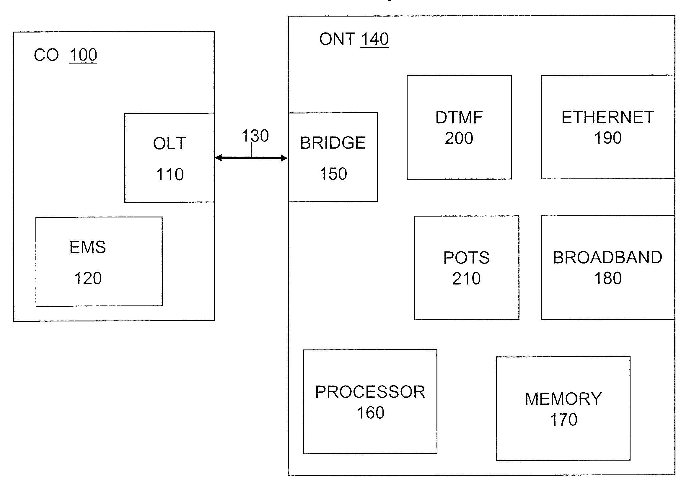
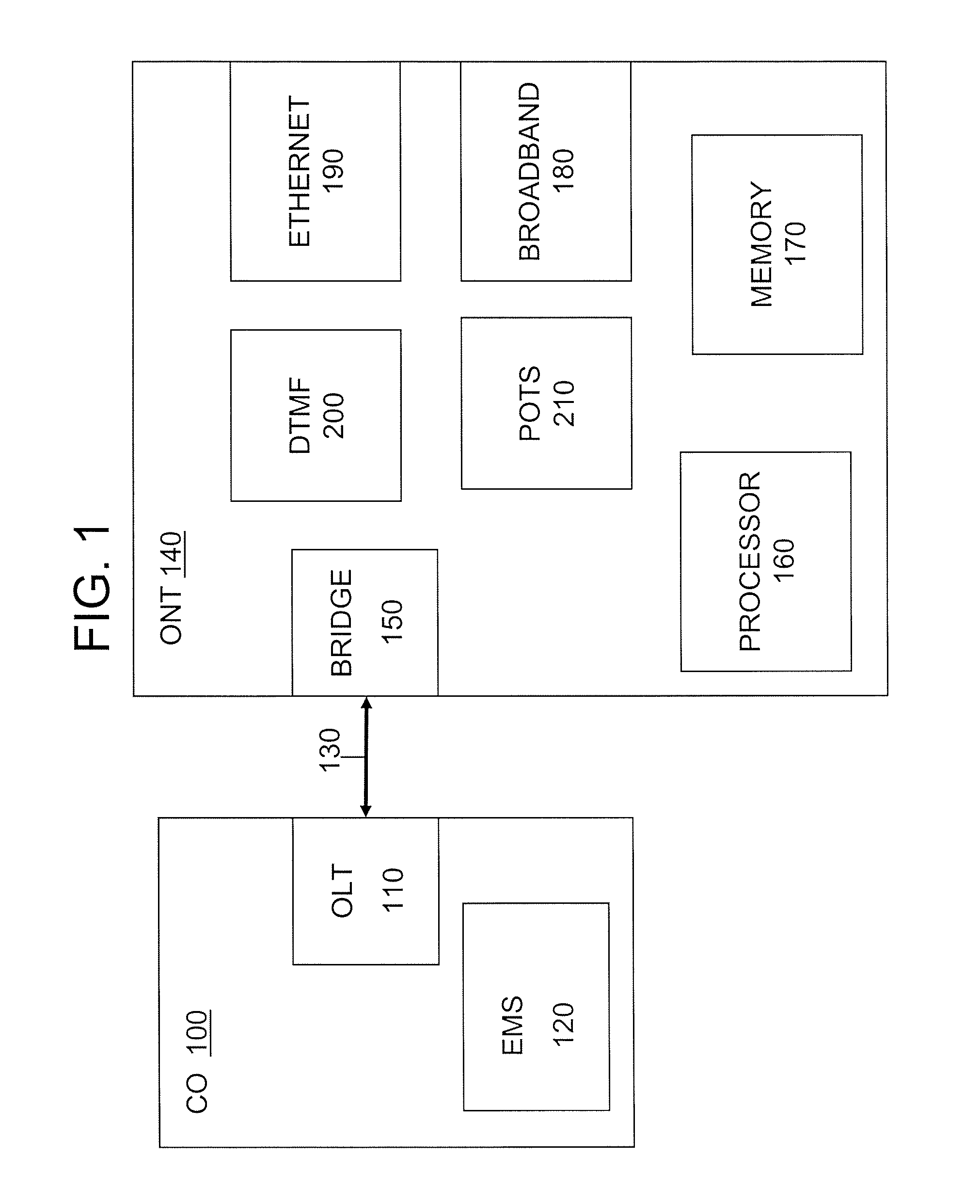
[0018]An example embodiment of the invention will be described with respect to FIG. 1. As shown in FIG. 1, a system for distributing data includes a central office 100, a data channel 130, and a network terminal 140. In this example embodiment, the data channel is a fiber link and the network terminal is an optical network terminal (ONT). However, those skilled in the art will appreciate that this is merely an example embodiment and the methods and apparatus described herein can be applied in environments other than optical networks.

[0019]Central office 100 includes an optical line terminal (OLT) 110 that can interface with plural data channels in communication with plural respective network terminals. The central office performs switching functions to manage the communication of data between service providers and end user locations where the respective network terminals are located. Although only one exemplary OLT is shown in FIG. 1, there may be many OLTs at a given central office...


PUM


Abstract

A method to initiate a remote diagnostic mode in a network terminal includes determining whether a received signal corresponds to a command to initiate a remote diagnostic mode, and setting the network terminal in a remote diagnostic mode in accordance with the result of the determining. An authentication procedure may be performed prior to setting the network terminal in the remote diagnostic mode, for increased security.

Description

BACKGROUND[0001]1. Field[0002]Example aspects of the present invention generally relate to diagnostic testing of a network terminal and, more particularly, to methods and apparatus to perform diagnostic testing of a network terminal involving access to remotely stored parameters.[0003]2. Description of the Related Art[0004]High bandwidth data is typically distributed over a high bandwidth channel, such as a fiber link, to a network terminal that provides an interface to a local area network (LAN). The network terminal includes an interface to receive data from the high bandwidth channel, as well as one or more interfaces for distributing data to a local network such as, for example, an Ethernet-based LAN and / or an in-home network for distribution of broadband video using coaxial cable. Configuration parameters for the network terminal are stored both locally at the network terminal and elsewhere on the network, e.g., at a central office. Data indicative of operating history (e.g., o...

Claims


Application Information

Patent Timeline
Patent Type & Authority Applications(United States)
IPC IPC(8): G06F15/16
CPCH04L12/2697H04L43/50H04L41/0856H04L41/0853
Inventor BERNARD, MARC R.NOEL, JEFFREY A.ROSENWALD, JEFFREYSTOCK, JOHN A.BURCH, JOHN T.
Owner TELLABS VIENNA
Why Eureka
Try Eureka