
Rack-and-pinion steering apparatus

a steering apparatus and rack and pinion technology, applied in the direction of hoisting equipment, gearing, transportation and packaging, etc., to achieve the effect of preventing nois

Inactive Publication Date: 2009-04-30
HONDA MOTOR CO LTD
View PDF3 Cites 13 Cited by
  • Summary
  • Abstract
  • Description
  • Claims
  • Application Information

AI Technical Summary

Benefits of technology

[0008]Accordingly, the present invention has been made in view of the above known problems. An object of the present invention is to prevent noise from occurring due to the looseness of the rack guide fitted into the guide hole in the rack-and-pinion steering apparatus.
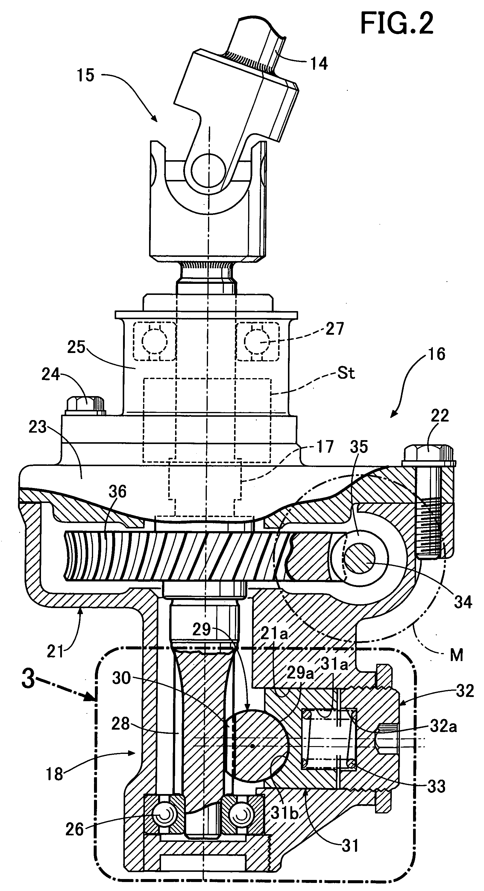
[0010]The configuration according to the first feature and aspect of the present invention causes the spring member to bias the cylindrical rack guide slidably fitted into the guide hole in the housing, and thus causes the rack guide to abut the rear part of the rack bar, while a steering torque acts on a part of the rack bar where the rack meshes with the pinion in such a way as to move the rack bar away from the pinion. Thereby, the meshing of the rack with the pinion can be kept in an appropriate condition. Particularly, the reaction force which the rack guide receives from the rack bar acts on the rack guide in such a way as to cause the rotation moment about the axis different from the axis of the rack guide. This makes the rack guide partially abut the guide hole, so that the rack guide and the guide hole are partially in tight contact with each other. Thereby, any looseness of the rack guide can be prevented, and vibration noise due to the looseness can thus be prevented.
[0014]The configuration according to the third feature and aspect of the present invention makes the reaction force, which the rack guide receives from the rack bar, cause the rotational moment which rotates the rack guide about the line of action of the reaction force. Thereby, this rotational moment causes the rack guide to partially abut the guide hole. As a result, the rotational moment based on the configuration according to the second aspect and feature of the present invention and the rotational moment about the line of action of the reaction force are generated simultaneously. Accordingly, vibration and noise due to the looseness can be prevented more reliably.
[0022]The configuration according to the seventh aspect and feature of the present invention causes a plurality of contact lines, extending in parallel with the axis of the rack bar, to protrude from the pressure surface of the rack guide, and thus makes these contact lines abut on the rear part of the rack bar. For this reason, resistance, which occurs when the rack guide and the rack bar slide on each other, can be reduced.

Problems solved by technology

The vibration brings about a problem of causing noise.

Method used


Image

  • Rack-and-pinion steering apparatus
  • Rack-and-pinion steering apparatus
  • Rack-and-pinion steering apparatus

Examples


Embodiment Construction

[0039]A first exemplary embodiment of the present invention will be described based on FIGS. 1 to 5.

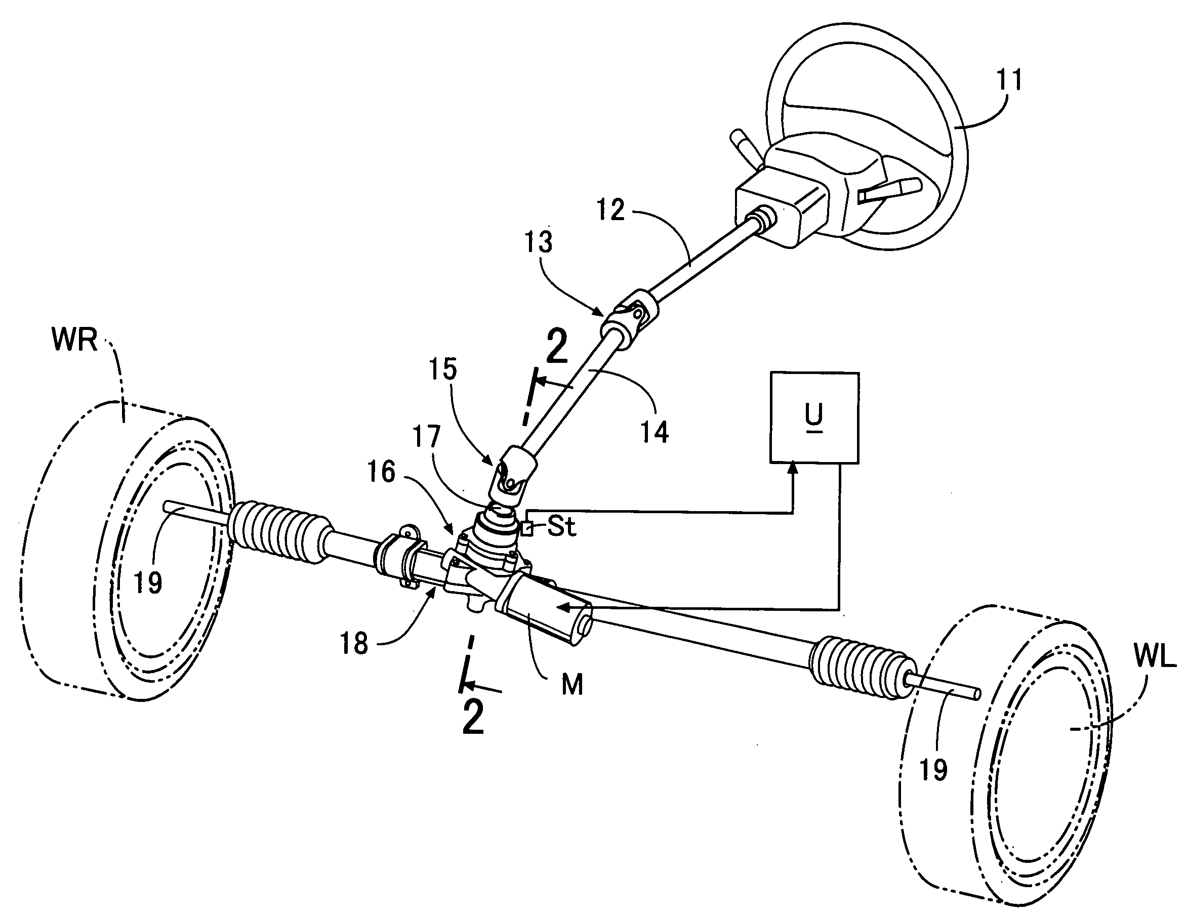
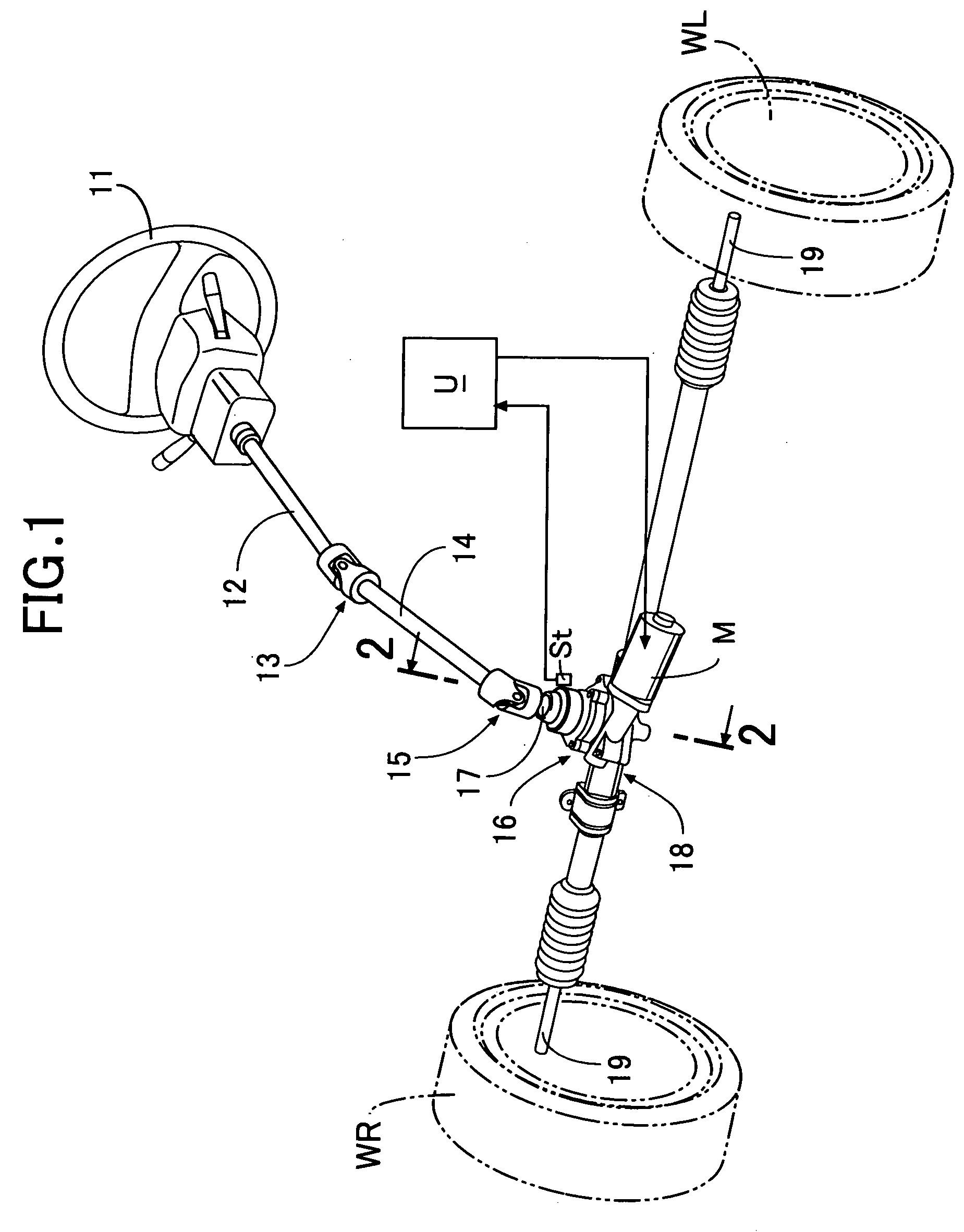
[0040]As shown in FIG. 1, an upper steering shaft 12 designed to rotate together with a steering wheel 11 is connected to a pinion shaft 17 protruding from a decelerator 16 via an upper universal joint 13, a lower steering shaft 14 and a lower universal joint 15. Tie rods 19, 19 protruding from left and right ends of a steering gear box 18 connected to the bottom tip of the decelerator or reduction gear 16 are connected to unillustrated knuckles of the left and right wheels WL, WR. An assist motor M configured of a brushless motor is supported by the decelerator 16. The operation of this assist motor M is controlled by an electronic control unit U into which a signal is inputted from steering torque detecting device St housed in the decelerator 16.

[0041]As shown in FIG. 2, the decelerator 16 includes: a lower housing 21 integrated with the steering gear box 18; an intermediate housing...


PUM


Abstract

A rack-and-pinion steering apparatus in which a steering gear box for transmitting an operation of a steering wheel to road wheels includes a pinion operatively connected to the steering wheel, a rack bar which has a rack meshing with the pinion, and which is operatively connected to the road wheels, a housing slidably supporting the rack bar, a cylindrical rack guide slidably fitted into a guide hole formed in the housing, and a spring member causing the rack guide to abut on a rear part of the rack bar opposite to the rack by biasing the rack guide. A reaction force, which the rack guide receives from the rack bar, acts on the rack guide in such a way as to cause a rotational moment of the rack guide about an axis different from an axis of the rack guide.

Description

CROSS-REFERENCE TO RELATED APPLICATIONS[0001]The present invention claims priority under 35 USC §119 based on Japanese patent application No. 2007-269670 filed 17 Oct. 2007. The subject matter of this priority document is incorporated by reference herein.BACKGROUND OF THE INVENTION[0002]1. Field of the Invention[0003]The present invention relates to a rack-and-pinion steering apparatus in which a steering gear box for transmitting an operation of a steering wheel to road wheels includes: a pinion operatively connected to the steering wheel; a rack bar which has a rack meshing with the pinion, and which is connected to the wheels; a housing for slidably supporting the rack bar; a cylindrical rack guide slidably fitted into a guide hole formed in the housing; and a spring member for causing the rack guide to abut on a rear of the rack bar by biasing the rack guide.[0004]2. Description of the Related Art[0005]A known rack-and-pinion steering apparatus is shown in Japanese Patent Applic...

Claims


Application Information

Patent Timeline
Patent Type & Authority Applications(United States)
IPC IPC(8): B62D3/12F16H55/26
CPCB62D3/123Y10T74/1967F16H55/286F16H55/283
Inventor MATSUO, TSUYOSHISHIMIZU, YASUOWATANABE, KATSUJI
Owner HONDA MOTOR CO LTD
Learn More