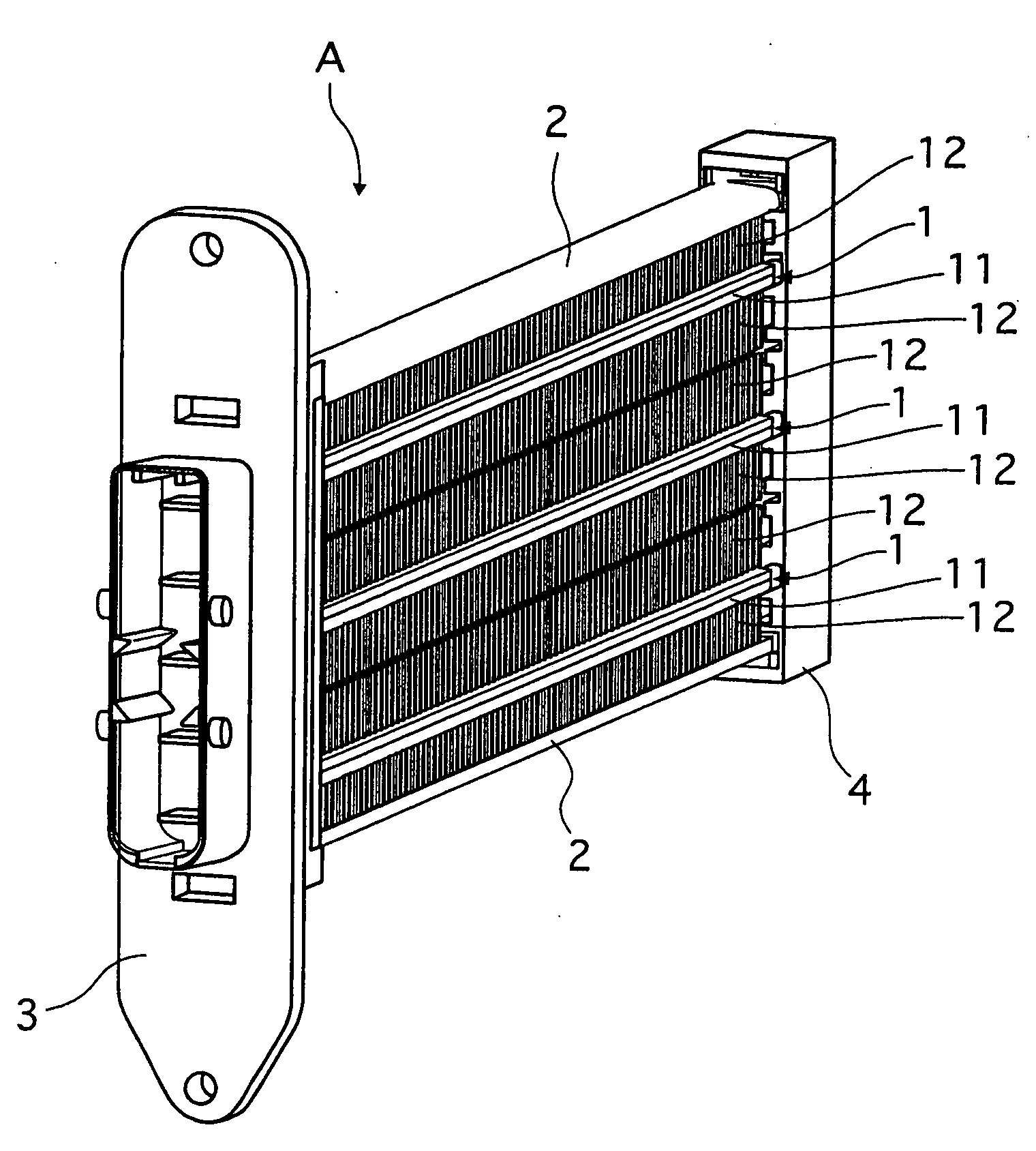
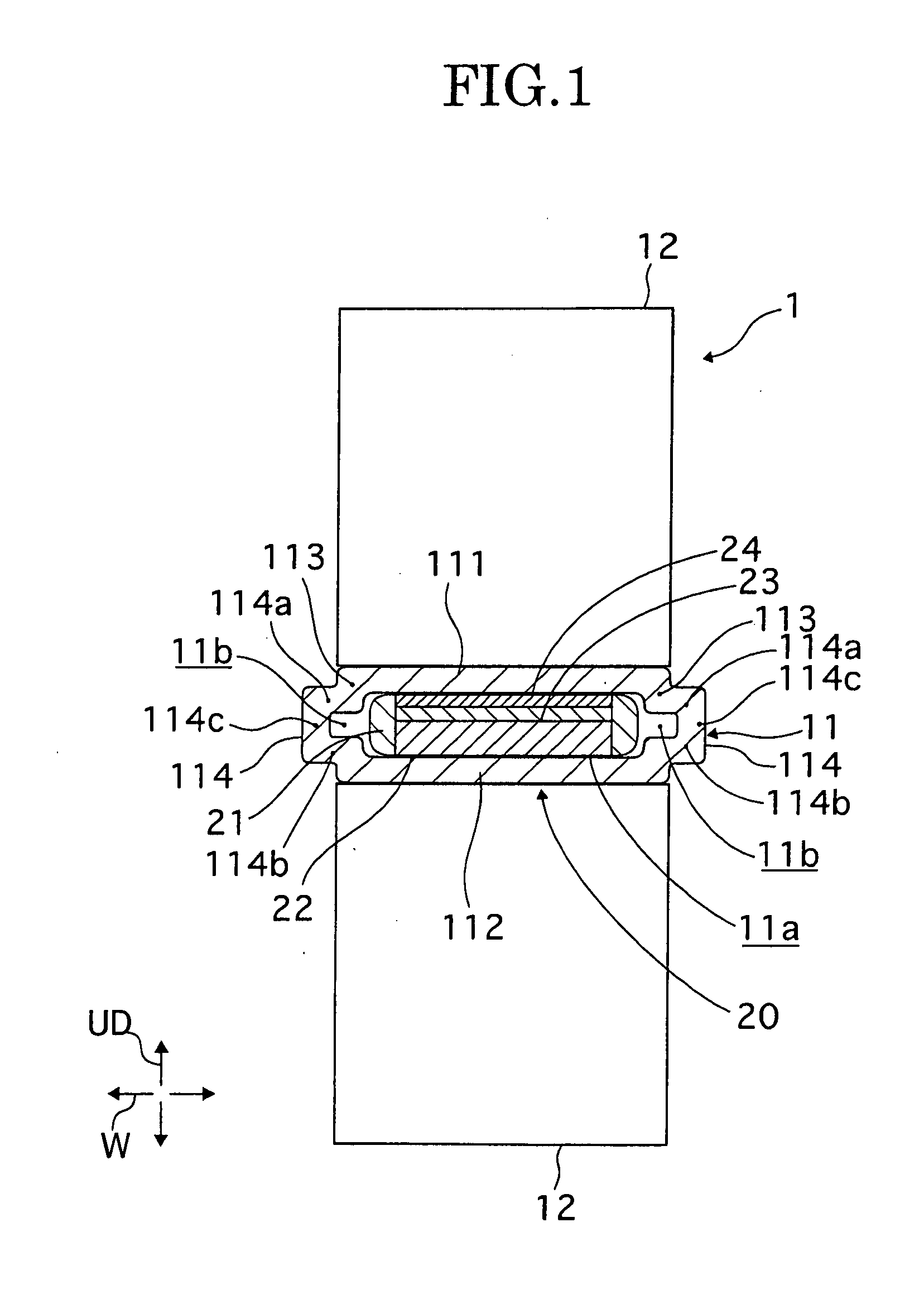
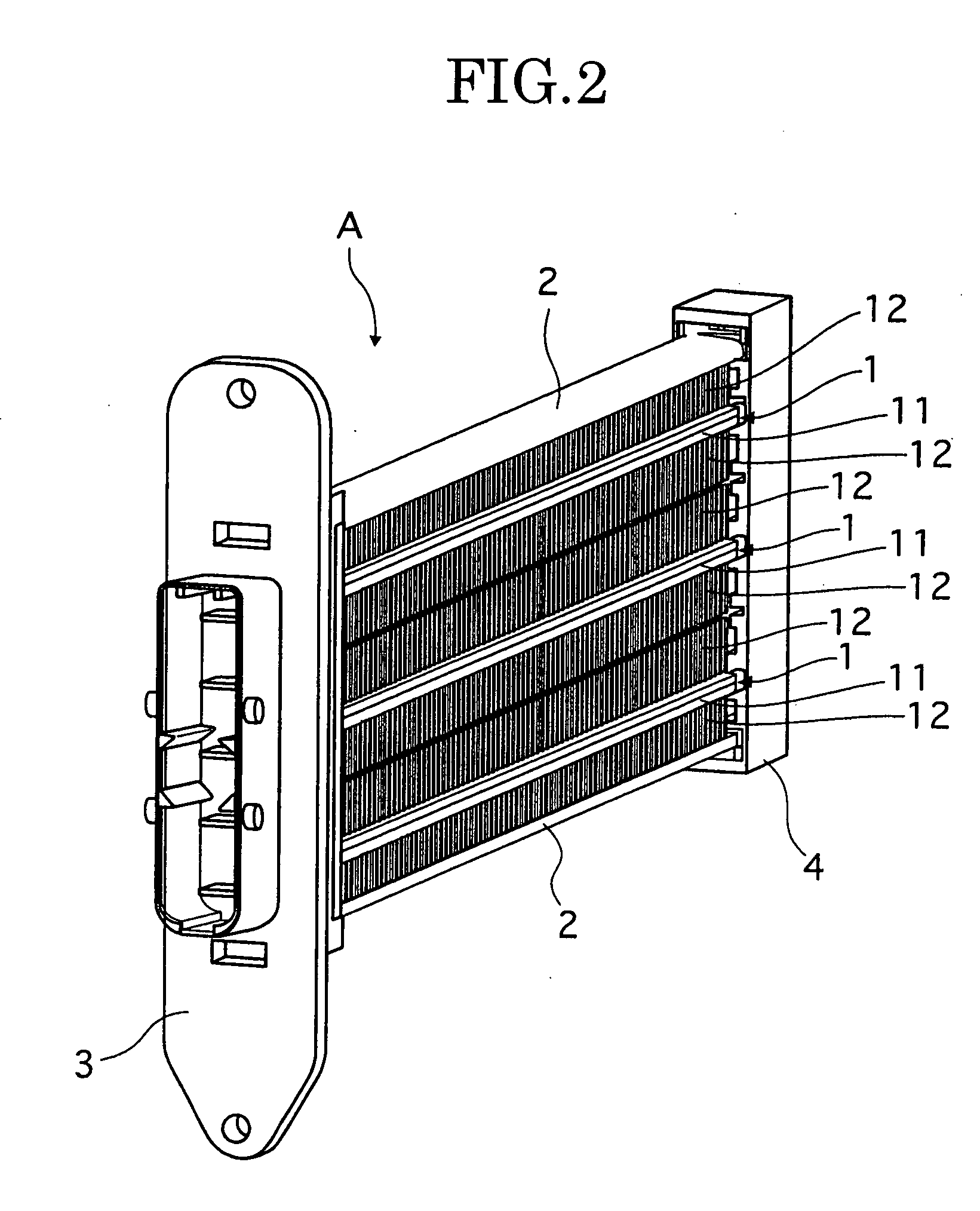
Electrical heating apparatus, method of manufacturing heat generator unit and pressing jig for use in manufacturing thereof

a technology of electric heating apparatus and heat generation unit, which is applied in the direction of heater elements, resistor housings/enclosements/embeddings, heater elements, etc., can solve the problems of insufficient heat generation, inability to smoothly energize and heat generation, and inability to achieve sufficient heat generation. , to achieve the effect of improving the heat generation performance of the electro-heat generation element and reducing the cos

Inactive Publication Date: 2009-04-30
CALSONIC KANSEI CORP
View PDF1 Cites 11 Cited by
  • Summary
  • Abstract
  • Description
  • Claims
  • Application Information

AI Technical Summary

Benefits of technology

[0014]The invention has been made by paying attention to the problems associated with the conventional art, and has an object of providing an electrical heating apparatus: in which the tube can be subjected to pressing (i.e., can be press-worked) after having brazed the fins to the tube; in which a contact pressure can be secured without subjecting the e

Problems solved by technology

This kind of conventional art has the following problems.
Electro-heat-generating element such as PTC element, can neither smoothly generate nor radiate heat when the contact pressure relative to the electrode plate and to the tube is lower than a set pressure, resulting in a problem in that a sufficient amount of heat generation cannot be attained.
In other words, when the contact pressure between the electro-heat-generating element and the tube is low, the heat generated in the electro-heat-generating element is not smoothly transmitted to the tube.
In this case, the temperature of the electro-heat-generating element itself becomes high, and the value of resistance becomes high and, consequently, the energization and heat generation cannot be smoothly performed.
In case the apparatus is provided with an urging member such as a spring for securing a contact pressure between the electro-heat-generating element and the tube, the number of constituent parts increases and the cost and weight increase.
In addition, in case both end portions are pressed so as not to pressurize the electro

Method used


Image

  • Electrical heating apparatus, method of manufacturing heat generator unit and pressing jig for use in manufacturing thereof
  • Electrical heating apparatus, method of manufacturing heat generator unit and pressing jig for use in manufacturing thereof
  • Electrical heating apparatus, method of manufacturing heat generator unit and pressing jig for use in manufacturing thereof

Examples


embodiment 2

[0085]With reference to FIG. 8, a description will now be made about the method of manufacturing the heat generator unit according to embodiment 2 of the invention.

[0086]Embodiment 2 is an example in which a substantially rectangular tube without the edge part 114 is employed as a tube 201 of a heat generator unit 200.

[0087]In other words, the tube 201 is formed into a substantially rectangular tube in cross section so as to enclose an insertion space 201a of substantially rectangular insertion space with a main body upper wall 202, main body lower wall 203, and main body vertical walls 204, 204.

[0088]Positioning groves 206, 206, 206, 206 to be used for positioning the width direction of the fins 12 are formed on widthwise both edge portions on an outside surface of the main body upper wall 202 and the main body lower wall 203. Also formed are convex strings 207, 207, 207, 207 which are projected on the inside surface of the widthwise both side edge portions.

[0089]On widthwise both ...


PUM

PropertyMeasurementUnit
Pressureaaaaaaaaaa
Thicknessaaaaaaaaaa
Pressureaaaaaaaaaa

Abstract

An electrical heating apparatus has: a fin brazed on at least one of a main body upper wall and a main body lower wall of a tube; an insertion unit having an electro-heat-generating element pressure-welded to a wall of one of the main body upper wall and the main body lower wall; and an edge part projected in the width direction from each of main body vertical walls to form an edge space. The edge space is formed so as to be continuous with the insertion space and is smaller in thickness dimension than the thickness dimension of the insertion unit. The edge part has an edge part upper wall, an edge part lower wall, and an edge part vertical wall disposed in a concave shape.

Description

CROSS REFERENCE TO RELATED APPLICATIONS[0001]The present application is based on and claims priorities from Japanese Application Numbers 2007-278499 and 2007-278500, both filed on Oct. 26, 2007, the disclosures of which are hereby incorporated by reference herein in their entirety.BACKGROUND OF THE INVENTION[0002]1. Field of the Invention[0003]The present invention relates to an electrical heating apparatus provided with a positive temperature coefficient (PTC) element which generates heat upon energization thereof (i.e., by passing electric current through the element). This element is called in the invention as an “energization heat-generating element” or “electro-heat-generating element.” The invention also relates to a method of manufacturing a heat generator unit as well as to a pressing jig for use in the method of manufacturing the heat generator unit.[0004]2. Description of the Related Art[0005]There is known in, e.g., JP-A-5-169967, an electrical heating apparatus comprisin...

Claims


Application Information

Patent Timeline
IPC IPC(8): H05B3/40H01S4/00
CPCY10T29/49002H05B3/50H05B2203/02
Inventor MORI, KAZUAKIABE, SYOTARO
Owner CALSONIC KANSEI CORP
Why Eureka
Try Eureka