
Method and apparatus for sensory stimulation

a sensory stimulation and apparatus technology, applied in the direction of tactile signalling system, visible signalling system, transmission, etc., can solve the problems of unreliable, difficult control, bulky moving mechanical components, etc., and achieve the effect of low power consumption

Active Publication Date: 2009-04-30
PIXART IMAGING INC
View PDF9 Cites 50 Cited by
  • Summary
  • Abstract
  • Description
  • Claims
  • Application Information

AI Technical Summary

Benefits of technology

[0021]In some embodiments the insulator comprises multiple layers. For instance, the inventors have discovered that the bulk of the insulator layer between the electrode and the body part approaching or toughing it may comprise glass but glass is not optimal as the insulator's surface material. In the present context, optimal means an insulator material which best supports the creation of the electrosensory sensation. A glass insulator works much better if covered with a plastic film.
[0026]For example, the invention differs from prior art solutions in that no touching or mechanical movement or vibration is required to generate the stimulus. Accordingly, the invention provides advantages over solutions which are based on, say, stroking the finger over the electrodes and on locally varying friction caused by the electric field. Furthermore, the various embodiments of the invention support solutions which are based not only on alternating current but also on direct current. Yet further, the inventive solution can be provided with a functionality to detect proximity and touch, whereby the same component can be used for input and output functions. In addition, various embodiments of the invention may utilize thick insulators, for example, which are mechanically stronger than thin insulators. Moreover, it has been discovered in connection with several embodiments of the invention that it is beneficial to use particular variation frequencies for the electric field, as they will enable smaller energy consumption in the generation of the stimulus.

Problems solved by technology

A problem shared by most such devices is that such moving mechanical members tend to be bulky, unreliable and / or difficult to control.

Method used


Image

  • Method and apparatus for sensory stimulation
  • Method and apparatus for sensory stimulation
  • Method and apparatus for sensory stimulation

Examples


Embodiment Construction

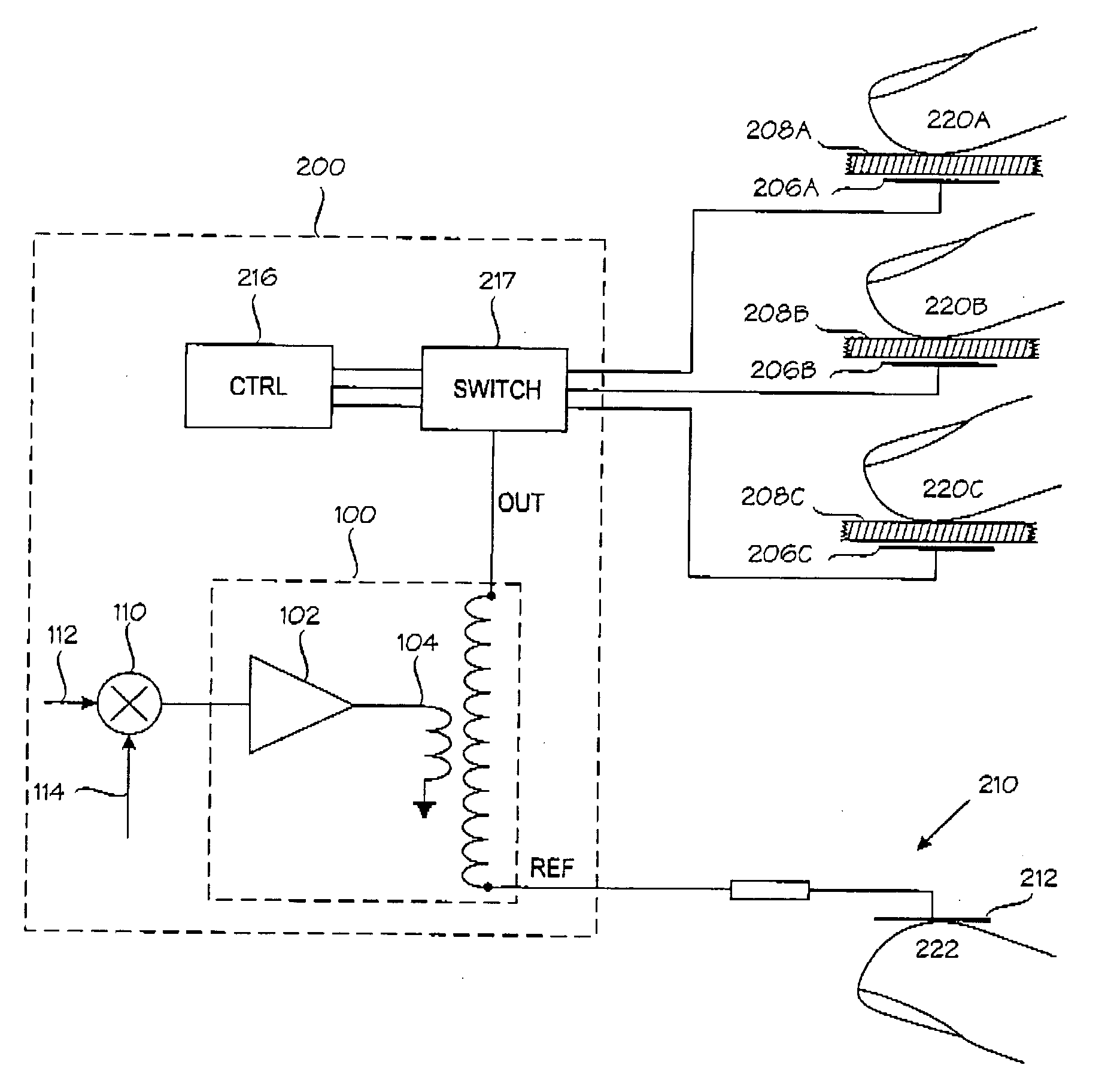
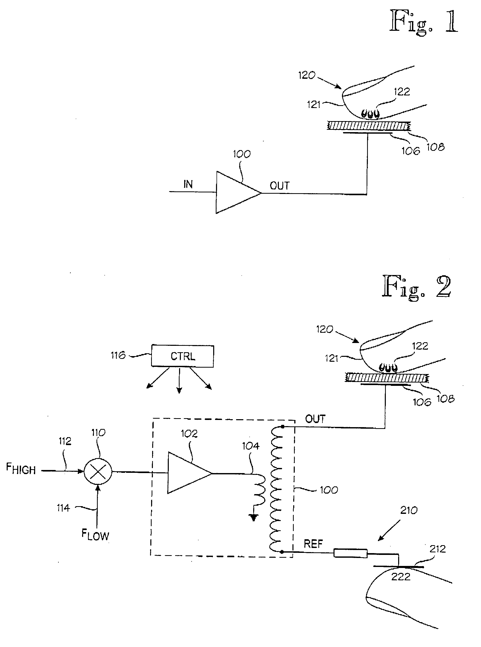
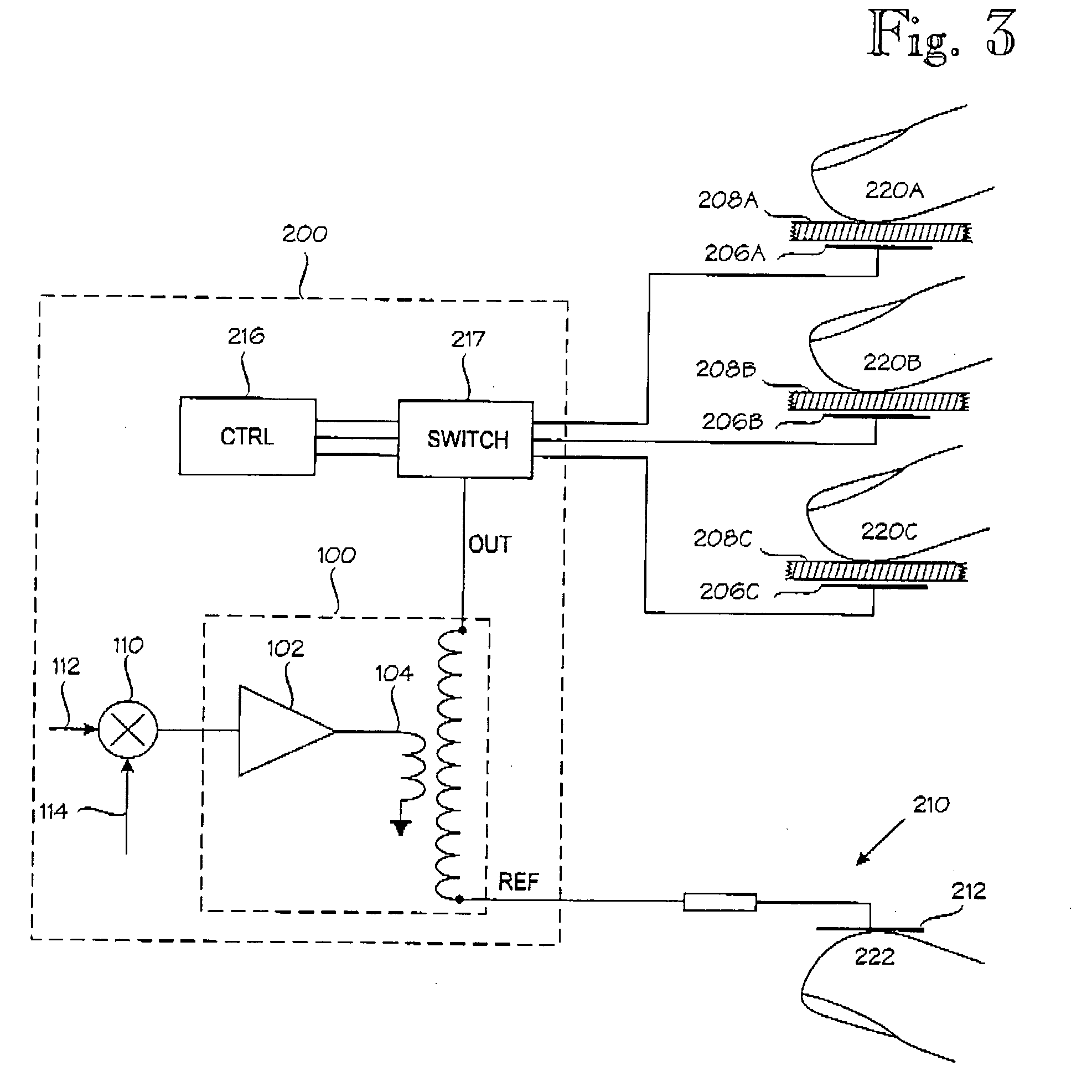
[0046]FIGS. 1 through 15 relate to the operation and implementation of a capacitive electrosensory interface (“CEI”) which can be employed in the inventive touch screen interface.

[0047]FIG. 1 illustrates the operating principle of the CEI. Reference numeral 100 denotes a high-voltage amplifier. The output of the high-voltage amplifier 100, denoted OUT, is coupled to an electrode 106 which is insulated against galvanic contact by an insulator 108 which comprises at least one insulation layer or member. Reference numeral 120 generally denotes a body member to be stimulated, such as a human finger. Human skin, which is denoted by reference numeral 121, is a relatively good insulator when dry, but the CEI provides a relatively good capacitive coupling between the electrode 106 and the body member 120. The capacitive coupling is virtually independent from skin conditions, such as moisture. The inventors' hypothesis is that the capacitive coupling between the electrode 106 and the body me...


PUM


Abstract

An apparatus for producing an electrosensory sensation to a body member (120). The apparatus comprises one or more conducting electrodes (106), each of which is provided with an insulator (108). When the body member (120) is proximate to the conducting electrode, the insulator prevents flow of direct current from the conducting electrode to the body member. A capacitive coupling over the insulator (108) is formed between the conducting electrode (106) and the body member (120). The conducting electrodes are driven by an electrical input which comprises a low-frequency component (114) in a frequency range between 10 Hz and 500 Hz. The capacitive coupling and electrical input are dimensioned to produce an electrosensory sensation. The apparatus is capable of producing the electrosensory sensation independently of any mechanical vibration of the one or more conducting electrodes (106) or insulators (108).

Description

BACKGROUND OF THE INVENTION[0001]The present invention relates to an apparatus and method for sensory stimulation. The invention is particularly applicable for stimulating the sense of touch.[0002]Manual input devices, such as joysticks and mice, are frequently complemented by means for providing tactile sensations such that the manual input devices provide tactile feedback to their users. There are hundreds of US patents for tactile feedback devices. In most or all of the prior art devices the tactile stimulation is generated by means of moving or vibrating mechanical members. A problem shared by most such devices is that such moving mechanical members tend to be bulky, unreliable and / or difficult to control.BRIEF DESCRIPTION OF THE INVENTION[0003]An object of the present invention is to provide a method and apparatus for alleviating at least one of the problems identified above.[0004]The object of the invention is achieved by features which are disclosed in the attached independen...

Claims


Application Information

Patent Timeline
Patent Type & Authority Applications(United States)
IPC IPC(8): G08B6/00G06F3/01
CPCG06F3/016G08B6/00G09B21/003G06F3/0416
Inventor MAKINEN, VILLESUVANTO, PETROLINJAMA, JUKKA
Owner PIXART IMAGING INC
Learn More