Liquid Ejecting Head and Liquid Ejecting Apparatus

Active Publication Date: 2009-04-30
SEIKO EPSON CORP
View PDF3 Cites 5 Cited by
  • Summary
  • Abstract
  • Description
  • Claims
  • Application Information

AI Technical Summary

Benefits of technology

[0010]An advantage of some aspects of the invention is that a liquid ejecting head and a liquid ejecting apparatus which are ab

Problems solved by technology

However, either of these filters might suffer from occurrence of warp (curl) at the time of manufacture.
Then, in the case of a structure in which a filter is joined on a substrate having ink flow channels such as the pressure generating chamber formed thereon, there arise problems such as defective joining caused by the curl of the filter (for example, separation of the filter) or deterioration of positioning accuracy of the filter with respect to the substrate, whereby desirable supply of ink to the reservoir via the filter might fail.
However, eve

Method used


Image

  • Liquid Ejecting Head and Liquid Ejecting Apparatus
  • Liquid Ejecting Head and Liquid Ejecting Apparatus
  • Liquid Ejecting Head and Liquid Ejecting Apparatus

Examples


first embodiment

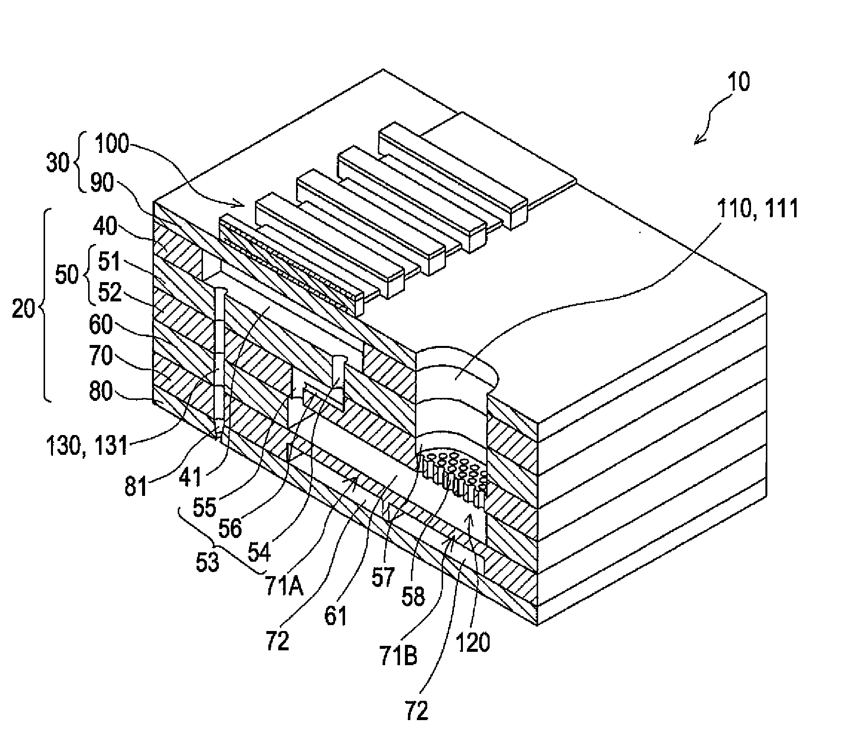
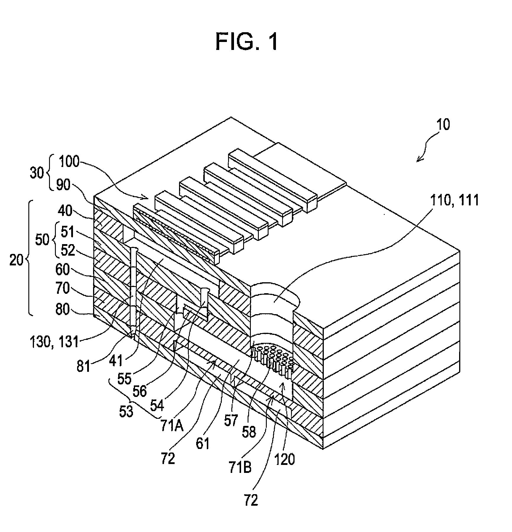
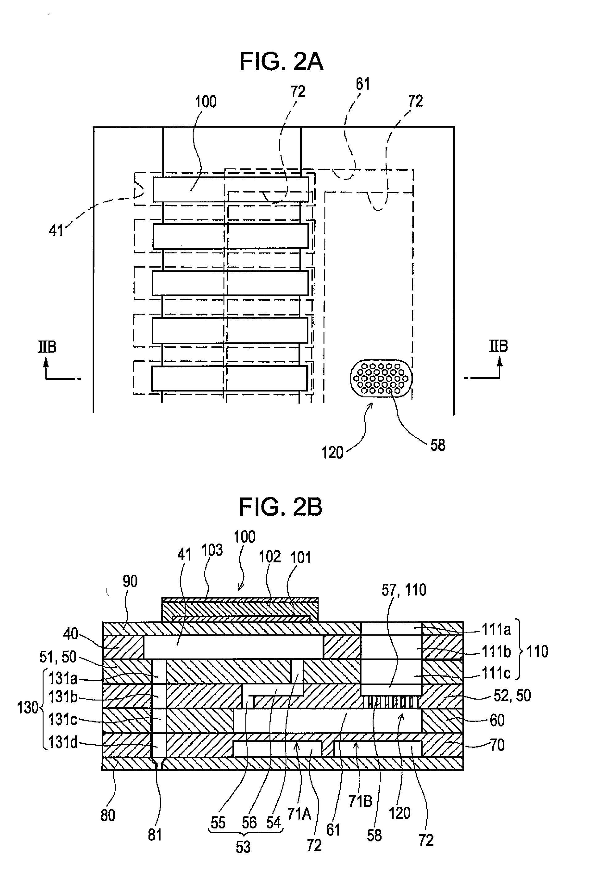
[0030]FIG. 1 is a schematic perspective view of an ink jet printhead as an example of a liquid ejecting head according to a first embodiment of the invention. FIG. 2A is a plan view of the ink jet printhead; and FIG. 2B is a cross-sectional view of the ink jet printhead taken along the line IIB-IIB in FIG. 2A.

[0031]As shown in the drawing, an ink jet printhead 10 in the first embodiment includes a flow channel unit 20 formed of a plurality of laminated metal plates and formed with an ink flow channel, and an actuator device 30 fixed to the flow channel unit 20.

[0032]The flow channel unit 20 includes a pressure chamber plate 40, a supply channel member 50 having first and second first supply channel plates 51 and 52, a reservoir plate 60, a compliance plate 70, and a nozzle plate 80.

[0033]The pressure chamber plate 40 is formed with a plurality of pressure generating chambers 41 which constitute part of the ink flow channel arranged in parallel in the direction of width thereof. The ...

second embodiment

[0052]FIG. 4 is a perspective view schematically showing an ink jet printhead according to a second embodiment, and FIGS. 5A and 5B are a plan view and a cross-sectional view taken along the line VB-VB, respectively.

[0053]The second embodiment is a modification of the compliance portion and other configurations are the same as in the first embodiment. As shown in FIG. 4 and FIGS. 5A and 5B, a compliance plate 70A includes a through hole 73 which penetrates through the compliance plate 70A in the direction of thickness in an area opposing the supply communication channel 110. This through hole 73 is formed to be slightly wider than the supply communication channel 110 in the opening surface area. A nozzle plate 80A in an area opposing the through hole 73 is provided with a recess 82 formed by removing part of the nozzle plate 80A in the direction of thickness. The bottom of the recess 82 corresponds to a compliance portion 83.

[0054]In the configuration in the second embodiment, a rel...


PUM


Abstract

A liquid ejecting head includes: a supply channel member including a plurality of supply channel plates, and the supply channel including supply holes provided through the respective supply channel plates and a supply groove formed by removing part of one of adjacent supply channel plates in terms of the direction of thickness thereof for communicating the respective supply holes; a pressure generating element that provides a pressure to the pressure generating chamber; a supply communication channel that connects a storage unit having the liquid stored therein and a reservoir, the supply communication channel being formed through a pressure chamber plate and the supply channel member in the direction of thickness thereof, the supply channel plates having the supply groove being formed with a recess having the substantially same depth as the supply groove at an area corresponding to the supply communication channel; and a filter unit having a plurality of filter holes provided on the bottom of the recess.

Description

CROSS REFERENCES TO RELATED APPLICATIONS[0001]The present invention claims priority on the basis of Japanese Patent Application No. 2007-276812 filed in the Japanese Patent Office on Oct. 24, 2007, the entire contents of which are incorporated herein by reference.BACKGROUND[0002]1. Technical Field[0003]The present invention relates to a liquid ejecting head and a liquid ejecting apparatus.[0004]2. Related Art[0005]As a representative example of a liquid ejecting head, an ink jet printhead of capable ejecting ink drops from nozzles is exemplified. The ink jet printhead generally includes a plurality of pressure generating chambers which communicate with nozzles and a reservoir (common ink chamber) which communicates the plurality of pressure generating chambers (cavity) respectively. Ink stored in a storage unit such as an ink cartridge is taken into the reservoir, is supplied from the reservoir to the respective pressure generating chambers, and is pressurized by a piezoelectric act...

Claims


Application Information

Patent Timeline
IPC IPC(8): B41J2/14
CPCB41J2/14233B41J2/17563B41J2202/11B41J2002/14403B41J2002/14419B41J2002/14306
Inventor NAGATE, TORUSAKAI, TOSHIFUMI
Owner SEIKO EPSON CORP
Why Eureka
Try Eureka