Timepiece including optical guide which performs the function of a crystal

a technology of optical guide and crystal, applied in the field of timepieces, can solve the problems of high manufacturing cost, complex optical system in terms of electrical connections, and the need for a method whose cost is not negligible, and achieve the effect of low cos

Active Publication Date: 2009-04-30
CORDIS CORP +1
View PDF25 Cites 17 Cited by
  • Summary
  • Abstract
  • Description
  • Claims
  • Application Information

AI Technical Summary

Benefits of technology

[0004]It is an object of the present invention to overcome the aforementioned drawbacks of the prior art by supplying a device, particularly for a timepiece, for displaying a decorative pattern that can be implemented at a lower cost.

Problems solved by technology

This system has, however, a certain number of drawbacks, including in particular high manufacturing cost.
Thus, deposition of the electrodes on the cell faces requires a method whose cost is not negligible, in particular if the optical system is to be implemented in a device for the general public at a low cost price.
Moreover, this optical system is very complex in terms of electrical connections as regards the electrical powering of the liquid crystal control electrodes.

Method used


Image

  • Timepiece including optical guide which performs the function of a crystal
  • Timepiece including optical guide which performs the function of a crystal
  • Timepiece including optical guide which performs the function of a crystal

Examples


Embodiment Construction

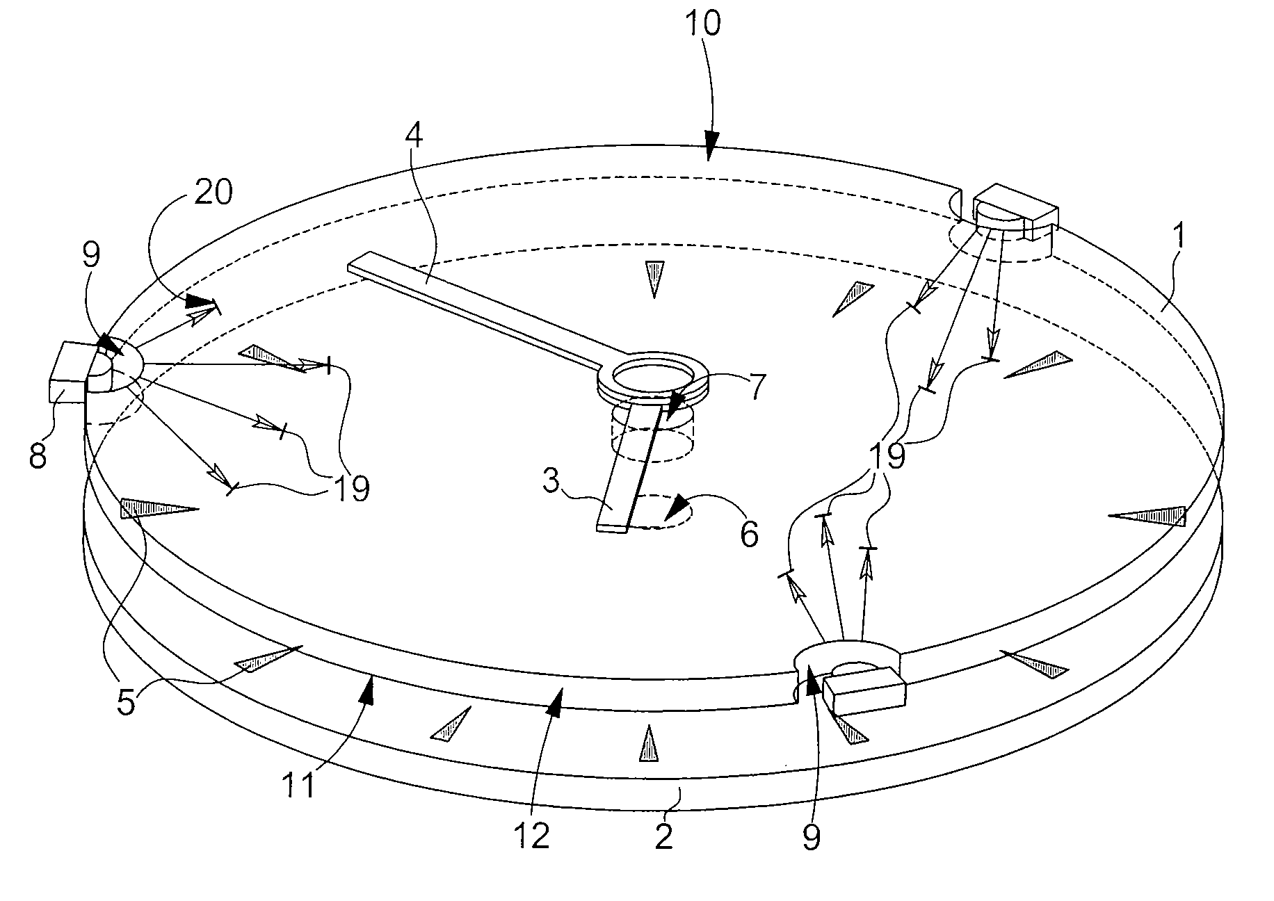
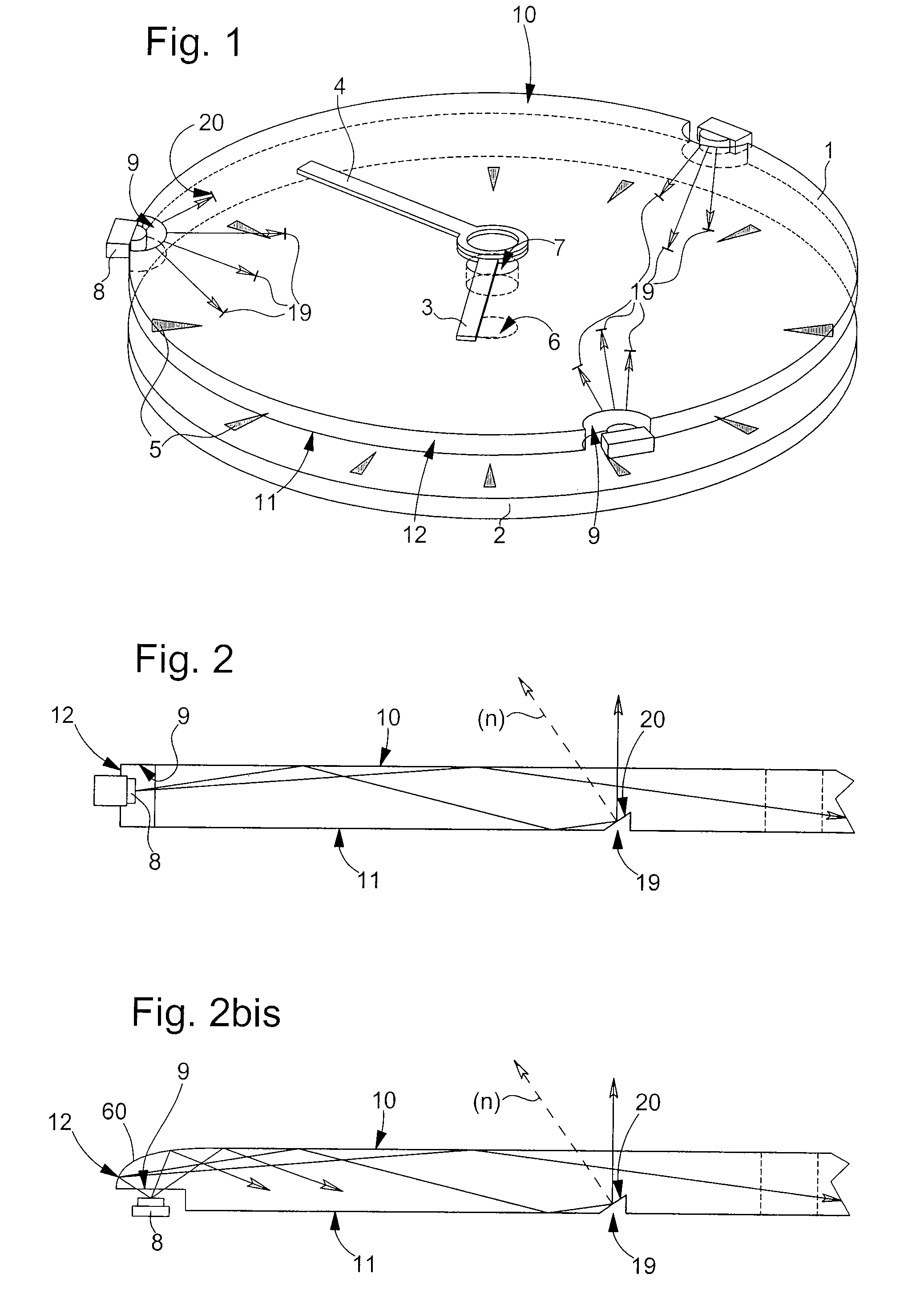
[0023]FIGS. 1 and 2 show schematic views respectively in perspective and cross-section of an optical guide 1 according to the present invention.

[0024]FIG. 1 shows a possible arrangement of optical guide 1 in a timepiece, namely between dial 2 and hour hand 3 and minute hand 4. Dial 2 and hands 3 and 4 are of a conventional type, dial 2 carrying hour symbols 5 for indicating the position of the hours.

[0025]The dial and the optical guide each include a central aperture respectively 6, 7, to allow drive means for hands 3 and 4 to pass, i.e. the hour wheel and the cannon-pinion (not shown in FIG. 1 for the sake of clarity).

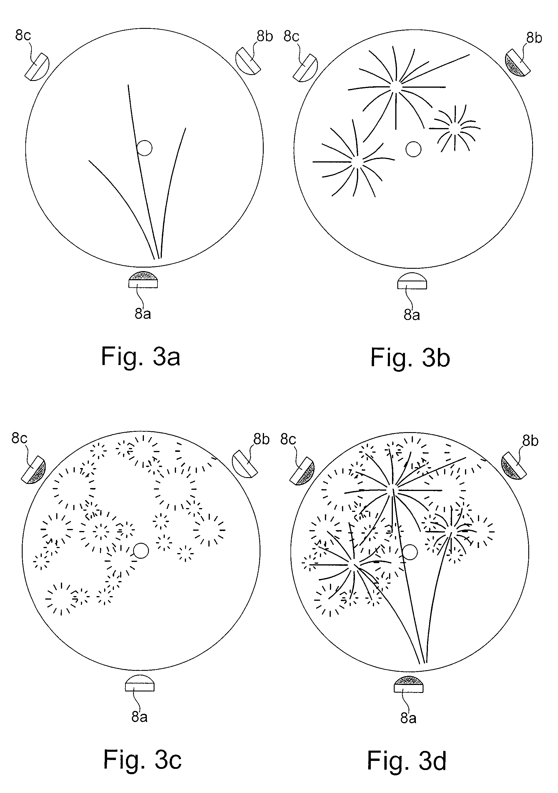
[0026]In the embodiment shown in FIG. 1, optical guide 1 operates in collaboration with three identical, or possibly different coloured, diodes 8, in order to form a figurative image visible above dial 2 of the timepiece.

[0027]From the point of view of the basic principle, a single diode 8 is sufficient to form, in association with a network of optical extractors as d...


PUM


Abstract

There is disclosed a timepiece (40) including optical means for forming a decorative pattern, in the form of a figurative image, in response to an action by the user. The optical means forming a figurative image include an optical guide (1, 51) having two large faces (10, 11) and at least one lateral face (12). Optical extractors (19) each having at least one light reflective surface (20) are arranged in at least one of the large faces (11). A light source (8, 8a, 8b, 8c) is arranged so as to emit light in the direction of the reflective surfaces (20), via the lateral face (12) of the optical guide. Thus, each of the reflective surfaces causes a reflected light beam to form in a well defined direction, the set of light beams forming a figurative image in that direction, which can typically be selected as the normal with respect to the mid-plane of the watch.

Description

FIELD OF THE INVENTION[0001]The present invention concerns a timepiece including a case closed by a crystal and inside which there is housed an optical device for forming a figurative image visible through said crystal.BACKGROUND OF THE INVENTION[0002]Timepieces of this type are known from the prior art. By way of example, EP Patent Application No. 0 786 685, filed on 16 Jan. 1997 in the name of SMH Management Services AG, discloses a timepiece comprising a device displaying a coloured decorative pattern. This document implements an optical valve located between a film on which the decorative pattern is printed and the timepiece crystal. When the optical valve is not being supplied with electrical energy, it appears black whereas when it is being powered, it becomes transparent thus making the decorative pattern visible.[0003]This system has, however, a certain number of drawbacks, including in particular high manufacturing cost. The optical valve is preferably made in the form in a...

Claims


Application Information

Patent Timeline
Patent Type & Authority Applications(United States)
IPC IPC(8): G04B19/30G04G99/00
CPCG04B19/30G04G9/0041G04B45/0015G04G99/00
Inventor WINKLER, PASCAL
Owner CORDIS CORP
Why Eureka
Try Eureka