
System for visualizing regions of Interest in medical images

a visualization system and image technology, applied in the field of contrast visualization system, can solve the problem of small time window of the entire acquisition, and achieve the effect of maintaining concentration on the appearance of the imag

Active Publication Date: 2009-04-30
SIEMENS HEALTHCARE GMBH
View PDF21 Cites 47 Cited by
  • Summary
  • Abstract
  • Description
  • Claims
  • Application Information

AI Technical Summary

Problems solved by technology

However, a drawback associated with this type of visualization is that only a small time window of the entire acquisition may be of interest.

Method used


Image

  • System for visualizing regions of Interest in medical images
  • System for visualizing regions of Interest in medical images
  • System for visualizing regions of Interest in medical images

Examples


Embodiment Construction

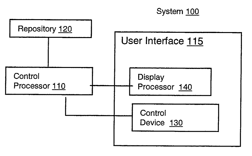
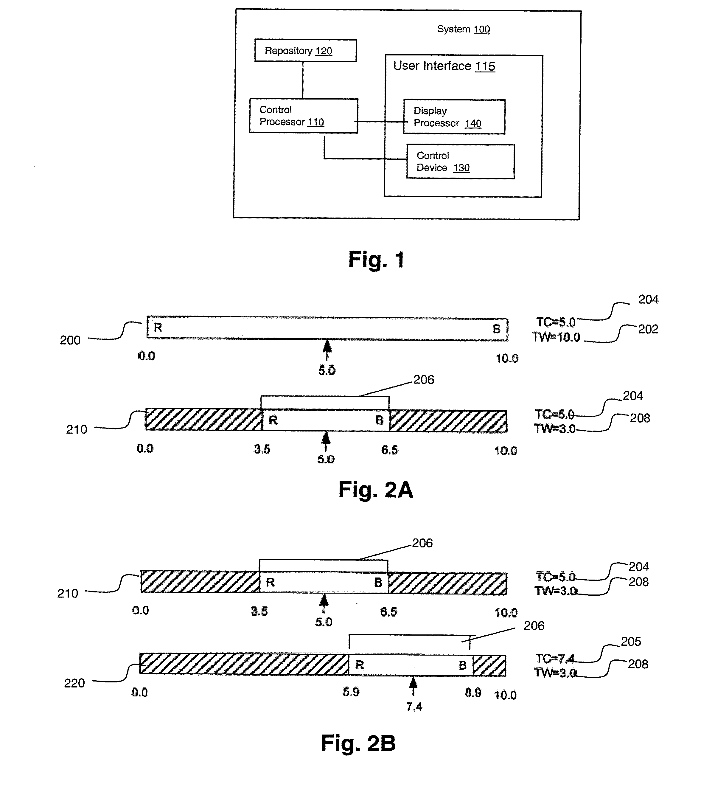
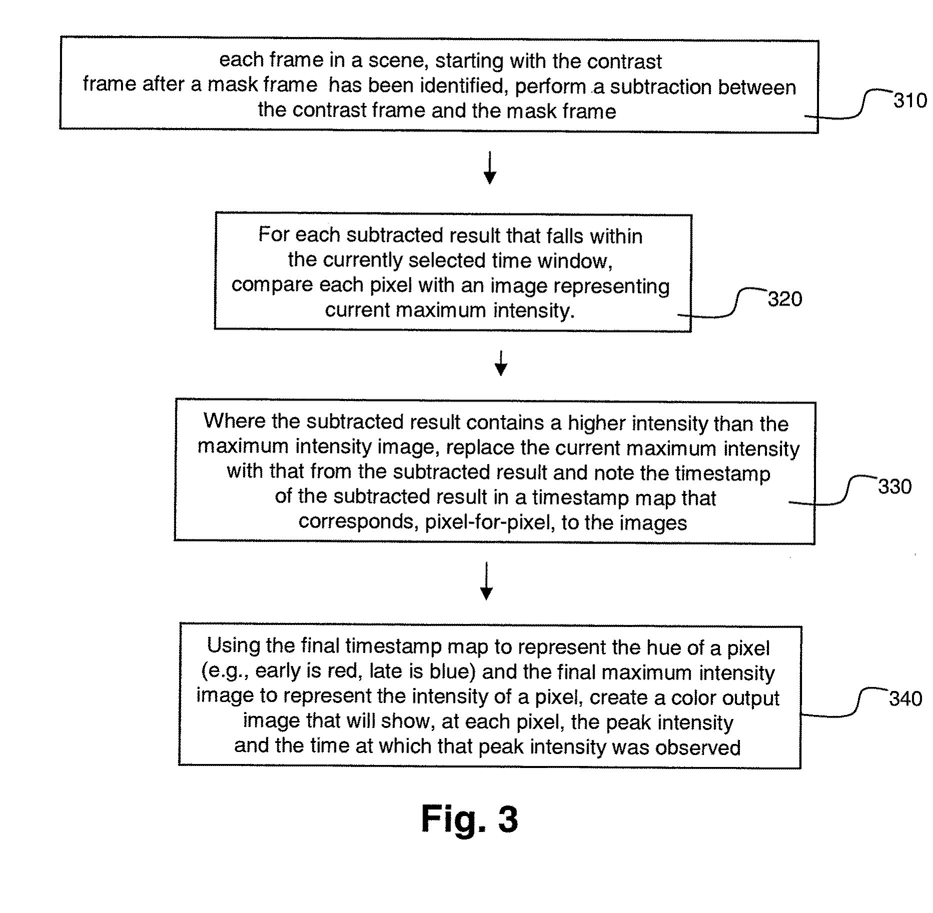
[0015]A processor as used herein is a device for executing stored machine-readable instructions for performing tasks and may comprise any one or combination of, hardware and firmware. A processor may also comprise memory storing machine-readable instructions executable for performing tasks. A processor acts upon information by manipulating, analyzing, modifying, converting or transmitting information for use by an executable procedure or an information device, and / or by routing the information to an output device. A processor may use or comprise the capabilities of a controller or microprocessor, for example. A processor may be coupled (electrically and / or as comprising executable components) with any other processor enabling interaction and / or communication there-between. A user interface processor or generator is a known element comprising electronic circuitry or software or a combination of both for generating display images or portions thereof. A user interface comprises one or ...


PUM


Abstract

A system for visualizing vascular fluid flow concentration includes at least one repository including a plurality of stored angiography scenes, an angiography scene comprises a plurality of individual images of a vascular structure successively acquired over a time period. A user interface control device enables a user to determine, (a) a duration and (b) a start time relative to a start time of the time period, of a window of interest within the time period. A control processor is electrically coupled to the user interface control device and the at least one repository. Control processor automatically assigns a unique visual indicator representing contrast flow of fluid through vessels to individual images within the user determined duration of the time period. A display processor, electrically coupled to the control processor and the user interface control device and at least one repository, generates data representing at least one display image comprising a composite image including individual images within the user determined duration of the time period having a unique assigned visual indicator.

Description

[0001]This is a non-provisional application of provisional application Ser. No. 60 / 983,319 filed Oct. 29, 2007, by John Baumgart et al.FIELD OF THE INVENTION[0002]This invention concerns a system for visualizing contrast flow of fluids through vessels during an angiography.BACKGROUND OF THE INVENTION[0003]X-ray angiography is performed to obtain an image of a vascular structure of a patient. An angiography enables a healthcare practitioner to obtain an image of particular blood vessels that supply blood to major organs such as the heart and brain, for example. Once obtained, the healthcare professional is able to review the flow of blood through the target vascular structures for diagnostic purposes. For example, angiographic images enable a healthcare professional to diagnose pathology of vessels such as blockage caused by plaque build up.[0004]Angiographic x-ray imaging operates similarly to conventional x-ray in that x-rays are generated by an x-ray tube and as they pass through ...

Claims


Application Information

Patent Timeline
Patent Type & Authority Applications(United States)
IPC IPC(8): G06K9/00G16H30/20G16H30/40G16H40/63
CPCA61B6/481A61B6/504G06F19/321G06T2219/2012G06Q50/24G06T2210/41G06T19/20G06F19/3406G16H40/63G16H30/40G16H30/20
Inventor BAUMGART, JOHNMARTUCCI, GARY S.
Owner SIEMENS HEALTHCARE GMBH
Learn More