Automatic Bottom Lock

Inactive Publication Date: 2009-04-30
KUSN LUCKY SEA IND
View PDF3 Cites 3 Cited by
  • Summary
  • Abstract
  • Description
  • Claims
  • Application Information

AI Technical Summary

Benefits of technology

[0010]The advantage of the present invention is that the present invention can automatically lock the container the carrier during the laying down the lifting up process of the container in multi-direction and a more reliable manner. More particularly, t

Problems solved by technology

The present bottom lock of the container used in all kinds of conveyance has to be operated manually, which means when laying down, the container can not lock with the car

Method used


Image

  • Automatic Bottom Lock
  • Automatic Bottom Lock
  • Automatic Bottom Lock

Examples


Embodiment Construction

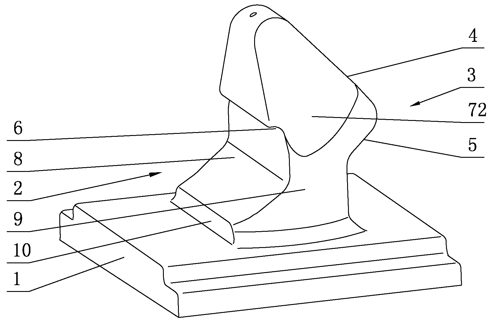
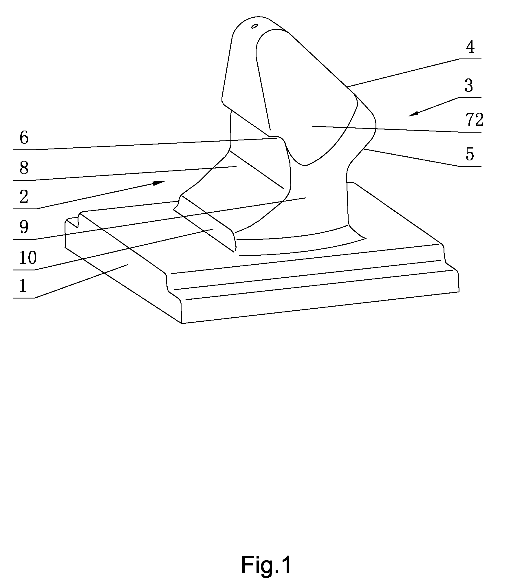
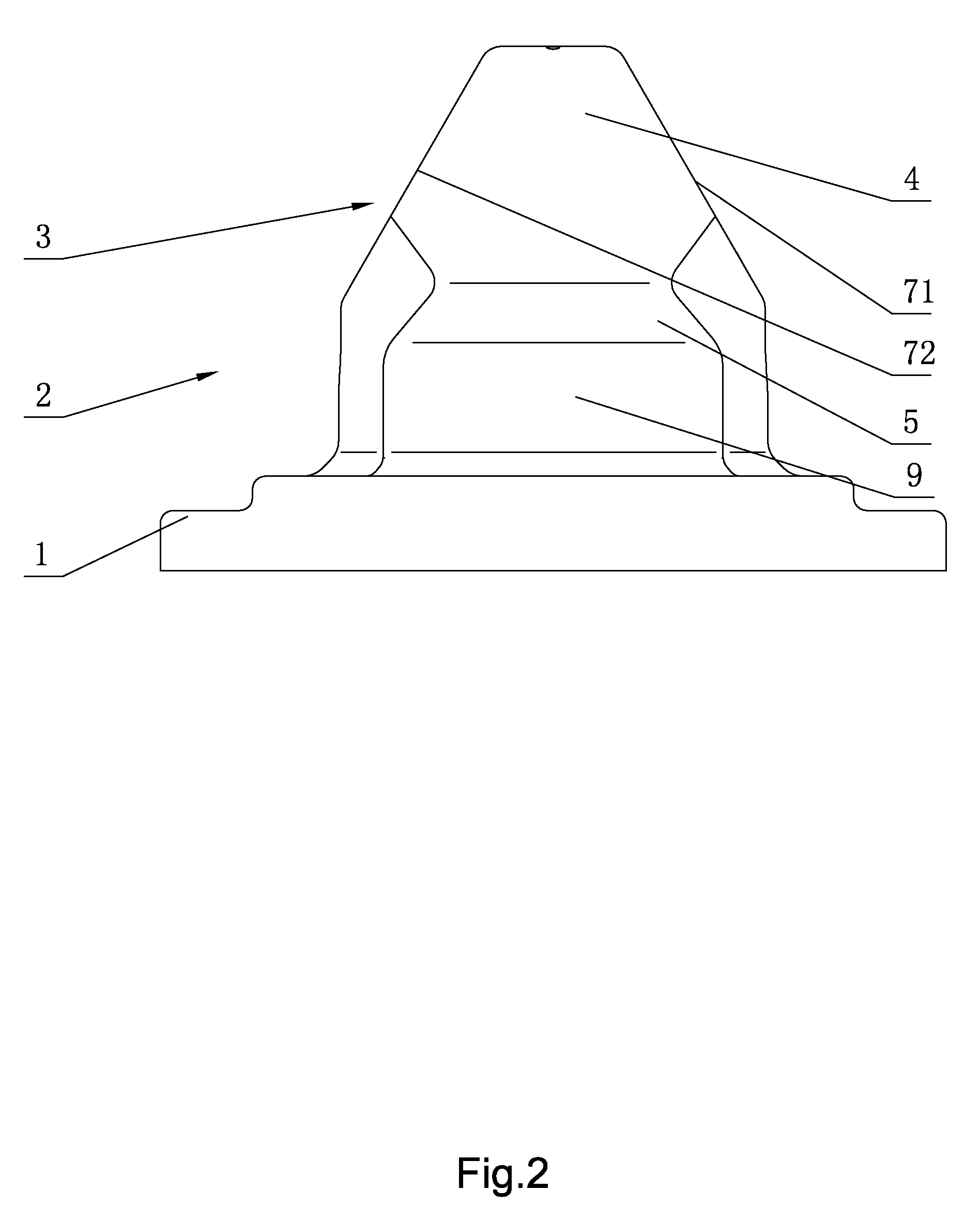
[0026]Referring to FIG. 1 through FIG. 5 of the drawings, an automatic bottom lock according to a preferred embodiment of the present invention is illustrated. The automatic bottom lock comprises a lock base 1, and a lock body 2 fastened above the lock base 1 comprising a hook provided thereon having a transverse guiding slope 4 extending forward and downwardly from a top at a front side of the hook, a hooking slope 5 extending backward and downwardly from a lower end of the transverse guiding slope 4, a transverse sliding slope 8 extending backward and downwardly from a top at a rear side of the hook, and a locating plane 10 at the bottom of the lock body 2 extending backward and downwardly from the transverse sliding slope 8, wherein the locating plane is vertical to the horizontal plane, and extends left and right along the lock body 2.

[0027]The hook 3 has a groove 6 indenting forward at a rear and middle part of the hook.

[0028]The hook 3 has a left longitudinal guiding slope71 e...


PUM


Abstract

The present invention provides an automatic bottom lock comprises a lock base, and a lock body fastened above the lock base comprising a hook provided thereon having a transverse guiding slope extending forward and downwardly from a top at a front side of the hook, a hooking slope extending backward and downwardly from a lower end of the transverse guiding slope, a transverse sliding slope extending backward and downwardly from a top at a rear side of the hook, and a locating plane at the bottom of the lock body extending backward and downwardly from the transverse sliding slope, wherein the locating plane is vertical to the horizontal plane, and extends left and right along the lock body.

Description

BACKGROUND OF THE PRESENT INVENTION[0001]1. Field of Invention[0002]The present invention relates to a container connector, and more particularly to an automatic bottom lock for locking a container in multi-direction at the bottom.[0003]2. Description of Related Arts[0004]At present, during the conveying of the container, a bottom lock is always provided at the bottom of the container for locking the container and the carrier, so as to prevent the shift and overturn of the container during the conveying.[0005]The present bottom lock of the container used in all kinds of conveyance has to be operated manually, which means when laying down, the container can not lock with the carrier automatically, and when lifting up, the container also can not unlock with the carrier automatically. This drawback directly affects a loading and unloading efficiency. Therefore, it is an advancement to develop an automatic bottom lock to load and unload the container efficiently.[0006]The patent applica...

Claims


Application Information

Patent Timeline
IPC IPC(8): B60P7/13B61D45/00
CPCB60P7/13
Inventor TANG, CHANGDE
Owner KUSN LUCKY SEA IND
Why Eureka
Try Eureka