Presser device with fabric guide

Active Publication Date: 2015-06-18
JANOME CORP
View PDF9 Cites 1 Cited by
  • Summary
  • Abstract
  • Description
  • Claims
  • Application Information

AI Technical Summary

Benefits of technology

The present invention is about a presser device with a fabric guide. This device has the advantages of simplified sliding and adjusting of the fabric guide body, and increased visibility of the guide scale. It includes a pressing hole that releases the pressure applied to the guide pin, and a lever that fixes and releases the fabric guide body to and from the guide pin. Additionally, a gauge is provided to support the fabric guide body in a stable manner. The technical effects of this invention include improved efficiency, accuracy, and reliability of the presser device with a fabric guide.

Problems solved by technology

However, since the blind-stitching presser tool described in the above Japanese Examined Utility Model Registration Application Publication No. 56-45578 adopts a mechanism that transversely moves the gauge with the adjustment screw, rattling in the transverse direction tends to occur and, further, when performing a considerably large degree of adjustment, the adjustment screw needs to be turned a number of times such that adjusting is disadvantageously arduous.
Furthermore in the stitch ruler described in the above Japanese Unexamined Patent Application Publication No. 10-295968, the screw needs to be retightened each time the position of the guide ruler is changed; accordingly, positioning of the guide ruler is bothersome.
Furthermore, while the stitch ruler described above is versatile and can be attached to a variety of fabric presser tools, the stitch ruler needs to be attached separate to the fabric presser tool and, disadvantageously, the stitch ruler may be lost when not used.
Furthermore, while the presser metal described in Japanese Examined Utility Model Registration Application Publication No. 52-710 can secure the fabric guide ruler to the fabric presser tool by mere application of a load to the fabric presser tool without the need for a presser screw and the like, when no load is applied to the fabric presser tool, disadvantageously, the fabric guide ruler unexpectedly moves with respect to the fabric presser tool.
Furthermore, since the presser including the edge guide described in Japanese Unexamined Utility Model Registration Application Publication No. 1-62780 (U.S. Pat. No. 4,899,677) carries out positioning of the slidable edge guide by engaging a lock unit with one of the grooves provided with a predetermined pitch between one another, disadvantageously, the lock unit cannot be set between the pitches and the edge guide cannot be set at a subtle position.
Furthermore, since fixing carried out with the lock unit is not strong, when the edge guide is unintentionally touched, the fixed position of the edge guide may be moved and the seam allowance may be changed, disadvantageously resulting in difficulty in repeating stitching with the same seam allowance.

Method used


Image

  • Presser device with fabric guide
  • Presser device with fabric guide
  • Presser device with fabric guide

Examples


first embodiment

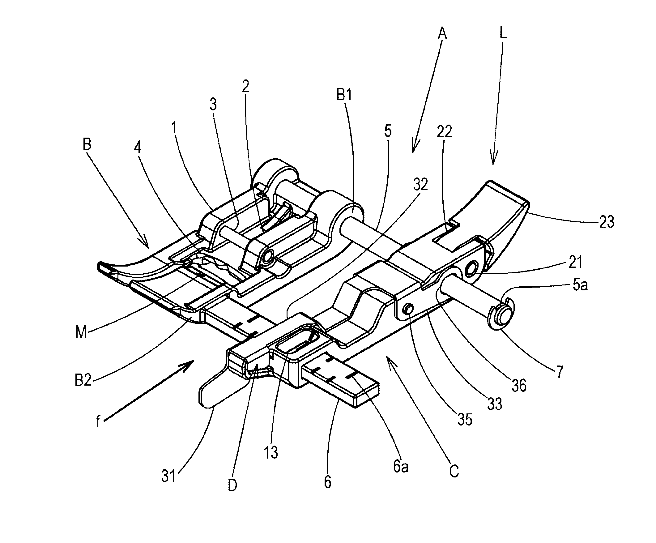
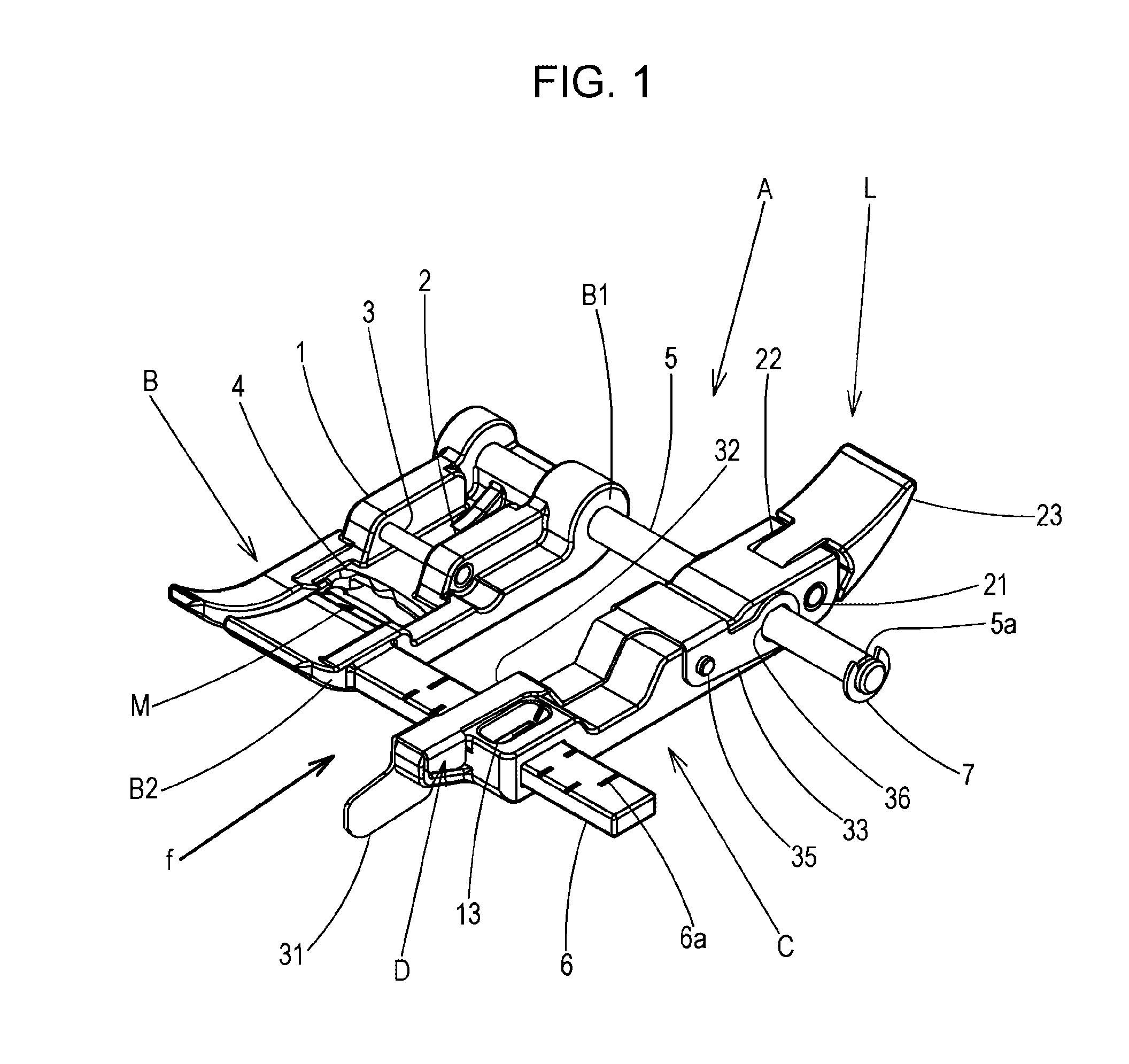
[0036]Referring to FIGS. 1 to 3, reference character A represents a presser device with a fabric guide, the presser device A being mounted at a lower end of a presser bar of a sewing machine so as to maintain a piece of fabric thereunder. The presser device A with a fabric guide includes a presser foot B, a fabric guide body C that is provided parallel to the presser foot B, the position of the fabric guide body C being slidably adjustable, and a guide pin pressing plate D that is pivotally fitted to the fabric guide body C.

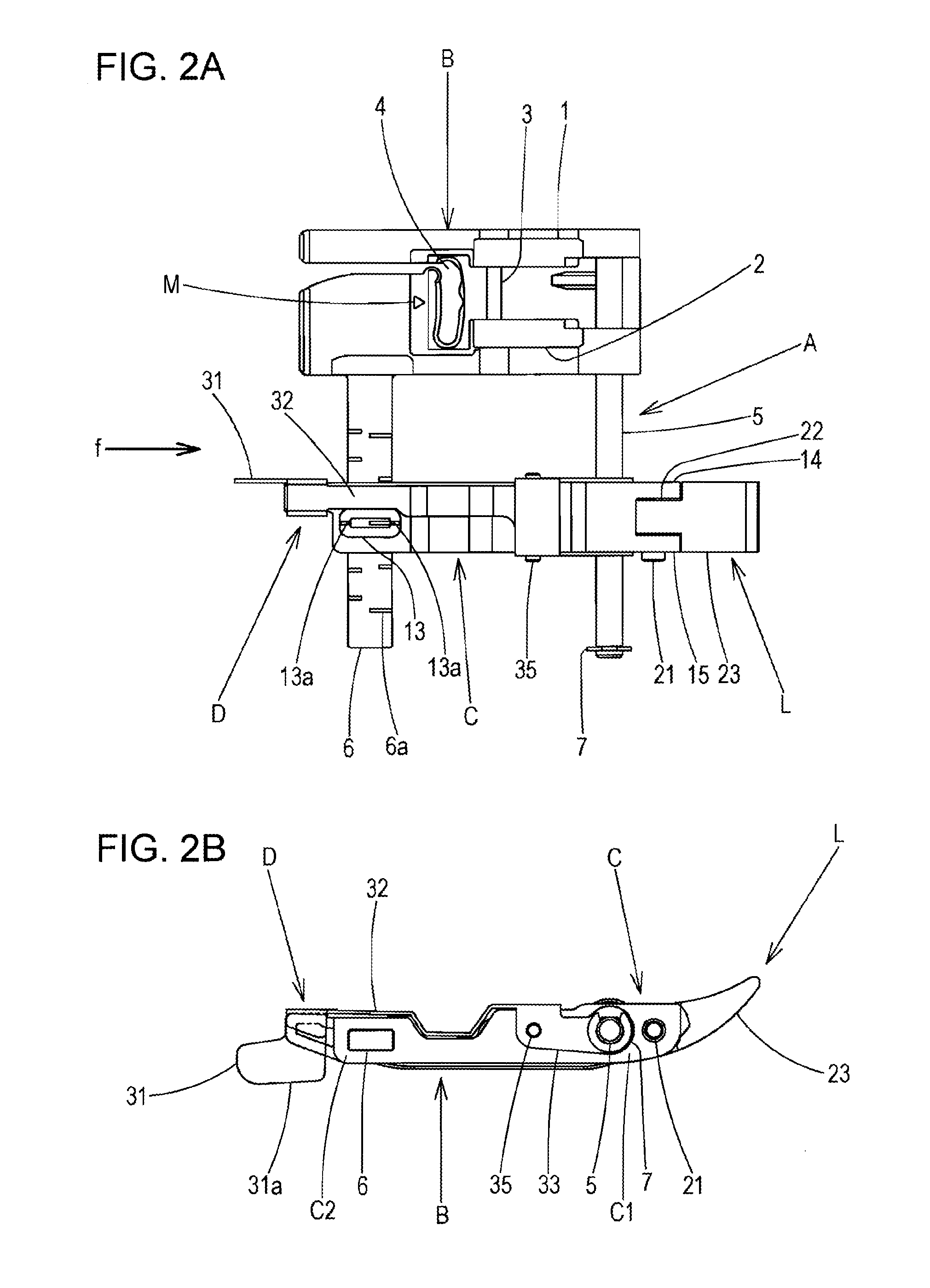
[0037]Note that in the following description, the left-hand side of FIG. 2A that is a top view is referred to as a “front”, the right-hand side thereof is referred to as a “rear”, the upper side thereof is referred to as a “left”, the lower side thereof is referred to as a “right”, and the up-down direction thereof is referred to as a “transverse direction”.

[0038]The presser foot B is formed of transparent synthetic resin and has a plate shape having a warped tip...

second embodiment

[0075]A second embodiment added with a guide plate that is separate from the guide pin pressing plate of the first embodiment will be described next.

[0076]In the present embodiment, components that are the same as the first embodiment will be designated with the same reference numerals and will be illustrated in the drawings while description thereof are omitted, and points that are different will be mainly described.

[0077]Referring to FIG. 6, reference character A represents the presser device with a fabric guide. The presser device A includes the presser foot B, the fabric guide body C that is provided in a parallel manner to the presser foot B, the position of the fabric guide body C being slidably adjustable, a guide pin pressing plate E that is pivotally fitted to the rear portion of the fabric guide body C, and a guide plate G that is attached to the front portion of the fabric guide body C.

[0078]The cylindrical metal guide pin 5 extending from the rear lateral side portion B1...

third embodiment

[0096]A third embodiment that is an embodiment in which the configuration of the guide pin pressing plate has been changed with respect to that of the second embodiment will be described next.

[0097]In the present embodiment, components that are the same as the first and second embodiments will be designated with the same reference numerals and will be illustrated in the drawings while description thereof are omitted, and points that are different will be mainly described.

[0098]Referring to FIG. 7A, reference character A represents the presser device with a fabric guide. The presser device A includes the presser foot B, the fabric guide body C that is provided in a parallel manner to the presser foot B, the position of the fabric guide body C being slidably adjustable, a guide pin pressing plate F that is pivotally fitted to the rear portion of the fabric guide body C, and a guide plate G that is attached to the front portion of the fabric guide body C.

[0099]The guide pin pressing pl...


PUM


Abstract

A presser device with a fabric guide including a presser foot mounted on a presser bar of a sewing machine; a fabric guide body provided parallel to the presser foot, a position of the fabric guide body being slidable and adjustable; a guide pin provided from a lateral portion of the presser foot in a direction orthogonal to a fabric feeding direction; the fabric guide body guiding an edge of a fabric, the guide pin being inserted through a guide hole of the fabric guide body; a guide pin pressing plate pivotally fitted to the fabric guide body. The guide pin pressing plate having a pushing-up portion that abuts against a needle plate and that exerts a pivoting force about a pivoting point, and a pressing hole through which the guide pin is inserted, the pressing hole applying pressing force to the guide pin.

Description

BACKGROUND OF THE INVENTION[0001]1. Field of the Invention[0002]The present disclosure relates to a presser device with a fabric guide that is mounted on a presser bar of a household sewing machine and that is used when carrying out edge stitching and, more particularly, relates to a presser device with a fabric guide that can slide and adjust a fabric guide body according to a distance (a seam allowance) from an edge of a fabric to a needle location.[0003]2. Description of the Related Art[0004]When carrying out edge stitching with a household sewing machine, stitching in a straight line needs to be carried out while keeping a constant distance from an edge of a fabric or from a stepped part where the fabric is folded back.[0005]Accordingly, the following assistive tools for facilitating edge stitching have hitherto been known.[0006]a. A blind-stitching presser tool for a sewing machine disclosed in Japanese Examined Utility Model Registration Application Publication No. 56-45578 th...

Claims


Application Information

Patent Timeline
IPC IPC(8): D05B29/06D05B29/12
CPCD05B29/12D05B29/06A41H1/00D05B35/10
Inventor YOKOYAMA, USHIOISHIKAWA, MUNEYUKITOYOMI, CHIYO
Owner JANOME CORP
Why Eureka
Try Eureka