
Method for Deploying A Device For Gastric Volume Reduction

a gastric volume and gastric bypass technology, applied in the field of gastric bypass surgery, can solve the problems of obesity affecting the personal contributing significantly to morbidity and mortality, and affecting the quality of life of individuals, and is estimated to cost an excess of $100 billion dollars annually in direct and indirect health care costs

Active Publication Date: 2009-04-30
ETHICON ENDO SURGERY INC
View PDF59 Cites 50 Cited by
  • Summary
  • Abstract
  • Description
  • Claims
  • Application Information

AI Technical Summary

Benefits of technology

[0009]A cartridge containing a fastener, wherein the cartridge releasably connected to a fastener deploying device. The cartridge has a housing which houses at least one tissue penetrating member. The penetrating member a

Problems solved by technology

Obesity affects an individual's personal quality of life and contributes significantly to morbidity and mortality.
Obesity and its co-morbidities are estimated to cost an excess of $100 billion dollars annually in direct and indirect health care costs.
These complications can affect all systems of the body, and dispel the misconception that obesity is merely a cosmetic problem.
Studies have shown that conservative treatment with diet and exercise alone may be ineffective for reducing excess body weight in many patients.
This procedure is highly complex and is commonly utilized to treat people exhibiting morbid obesity.
The conventional RYGB procedure requires a great deal of operative time and is not without procedure related risks.
Because of the degree of invasiveness, post-operative recovery can be quite lengthy and painful.
Still more than 100,000 RYGB procedures are performed annually in the United States alone, costing significant health care dollars.
This procedure restricts the amount of food that passes from one section of the stomach to the next, thereby inducing an early feeling of satiety.
In addition to surgical complications, patients undergoing a gastric banding procedure may suffer from esophageal injury, spleen injury, band slippage, reservoir deflation / leak, and persistent vomiting.
These persons may be 20-30 pounds overweight and want to lose the weight, but have not been able to succeed through diet and exercise alone.
For these individuals, the risks associated with the RYGB or other complex procedures often outweigh the potential health benefits and costs.
Further, it is known that modest reductions in weight may significantly decrease the impact of co morbid conditions including, but not limited to type 2 diabetes mellitus.
However, operating solely within the interior of the gastric cavity limits the plication depth that can be achieved without cutting.
Furthermore, access and visibility within the gastric cavity is limited in a purely endoscopic procedure as the extent of the reduction increases.
While the GVR procedure can be performed using a needle and suture, such an approach requires a highly skilled surgeon and can be time consuming.

Method used


Image

  • Method for Deploying A Device For Gastric Volume Reduction
  • Method for Deploying A Device For Gastric Volume Reduction
  • Method for Deploying A Device For Gastric Volume Reduction

Examples


first embodiment

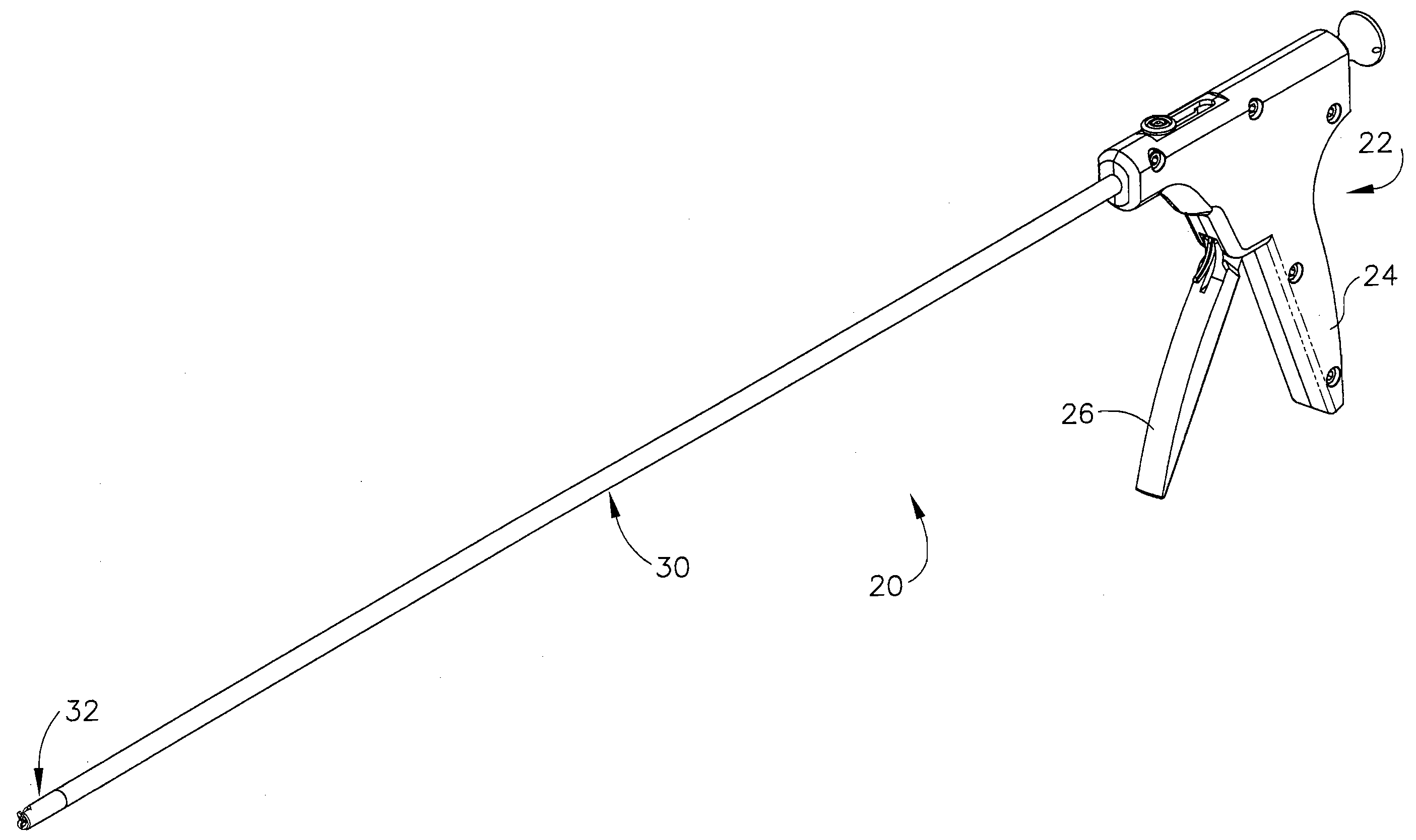
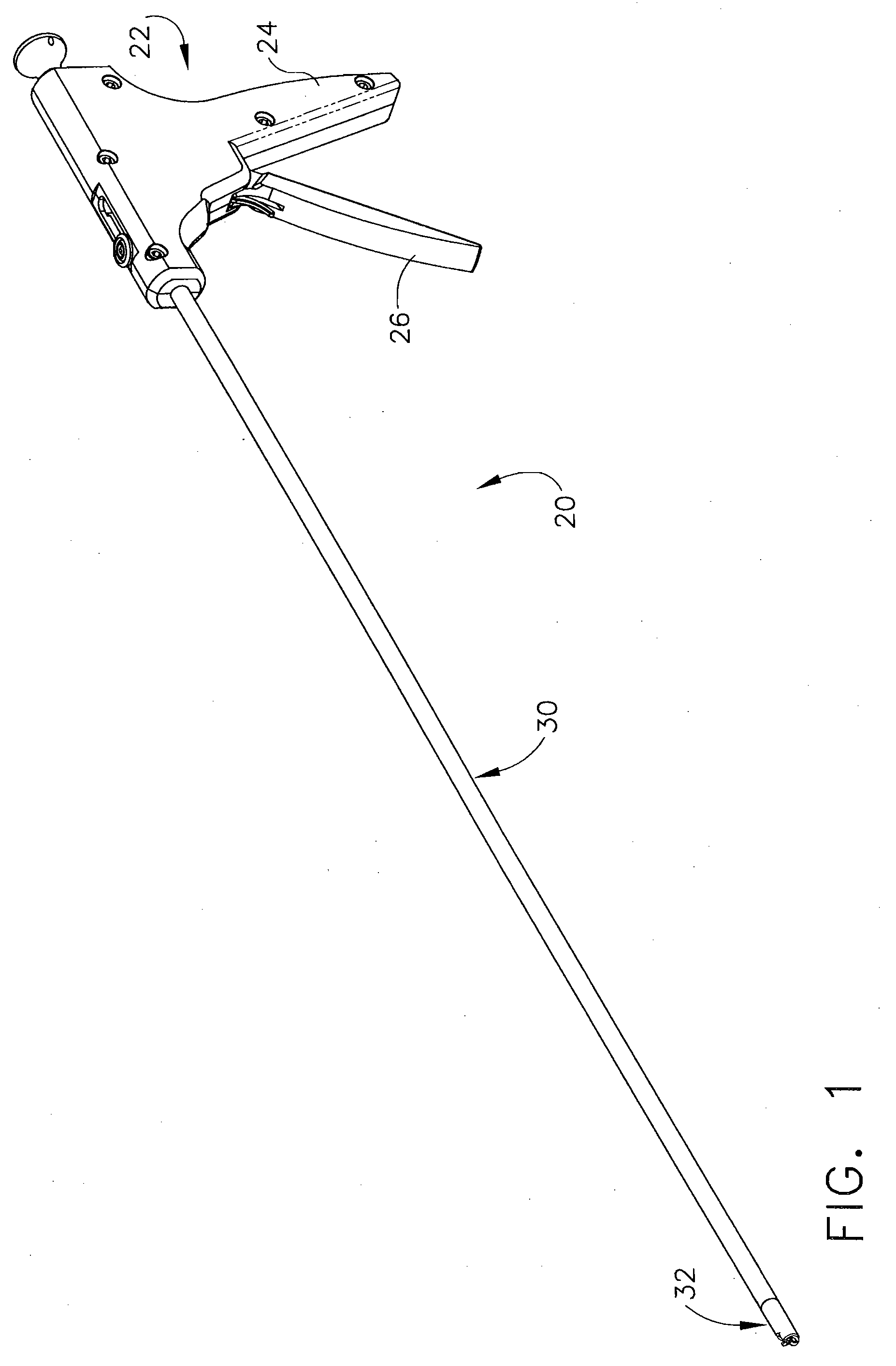
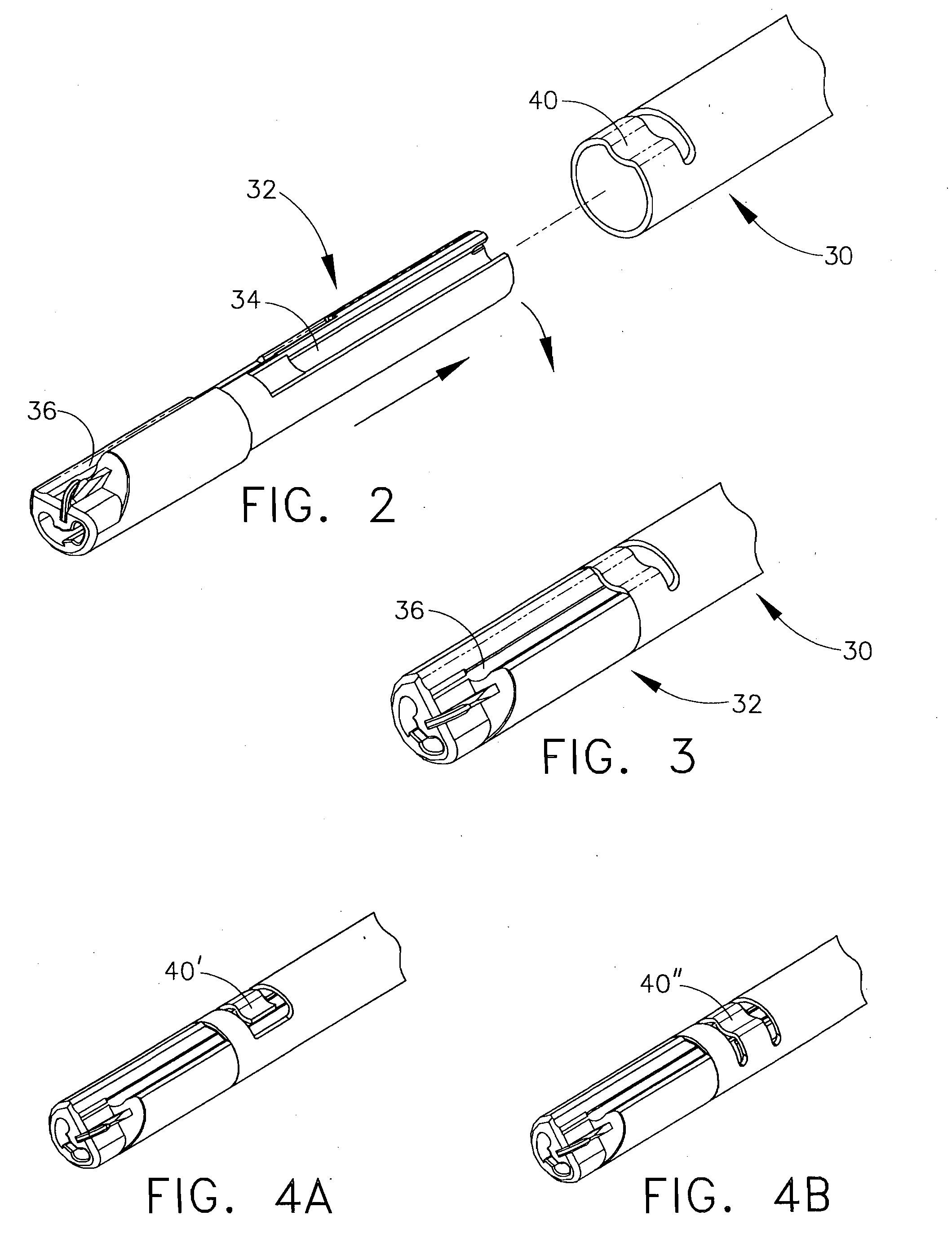
[0077]Fastener deploying device 20 is designed for use with a replaceable fastener cartridge. As shown in FIG. 1, the fastener cartridge 32 is releasably attachable to the distal end of housing 30. Cartridge 32 is sized and shaped for passage through a 3-5 mm trocar when attached to the deploying device. Coupling members are located on the distal end of housing 30 and the proximal end of cartridge 32 for releasably attaching the cartridge to the deploying device. The cartridge coupling members allow for a rapid and secure removal and replacement of a cartridge. FIGS. 2 and 3 are simplified views of cartridge 32 and housing 30, depicting a first embodiment for coupling a cartridge to the distal end of the housing. In this embodiment, the coupling members include a pair of circumferentially offset, longitudinally extending open channels on the body of the cartridge. A first one of the open channels 34 extends from the proximal end of the cartridge distally to a point just beyond the p...

second embodiment

[0106]After the second T-Tag anchor is deployed, the device can be reset to place push rod 140 back inside of housing 30. In the second embodiment described herein, the actuator further includes a secondary trigger 240. Secondary trigger 240 is located on the distal side of handle 22, between the primary trigger 26 and housing 30, and within easy reach by the same hand that grips the primary trigger. One of the functions of secondary trigger 240 is to control the resetting of the device. As shown in FIGS. 41-43, secondary trigger 240 includes a cam surface 274 at the fixed end of the trigger. Cam surface 274 rests against one end of a release post 276, which is contained within the primary trigger 26. With trigger 26 held in place by latching mechanism 280, the opposite end of release post 276 is in contact with the proximal end of drive pawl 160. With the primary trigger 26 held in place by the latching mechanism, the deploying device is reset by squeezing the secondary trigger 240...

fourth embodiment

[0117]FIG. 52 shows a fourth embodiment for the present invention, in which the deploying device is modified to include a protective outer sheath 290 that extends distally over the length of the cartridge. Outer sheath 290 extends proximally over housing 30 and is attached at a proximal end to button 132. In this embodiment, button 132 is attached to outer sheath 290 rather than housing 30, in order to retract and advance the outer sheath relative to the cartridge. Housing 30 is affixed in place within handle 22 by pins 300 located adjacent the proximal housing end, as shown in FIG. 53. A cutting means such as a V-notch 294 can be provided in the distal end of outer sheath 290 for severing suture following cinching. When button 132 is in a distal position, such as shown in FIG. 53, needle 52 is concealed within outer sheath 290. As button 132 is depressed to slide post 130 along track 134, the outer sheath 290 is retracted along the cartridge to expose needle 52 from the distal end ...


PUM


Abstract

A method for approximating tissue within a body including the step of providing a device having a handle, at least one actuator, an elongated hollow housing having a proximal end attached to the handle and a distal end extending therefrom, a first and second cartridge. Each the cartridge contains at least one fastener having at least two anchors connected together by a non-resilient flexible suture which does not resist deformation under compressible loads. The first cartridge being releasably connected to the distal end of hollow housing. The method also includes the step of inserting the first cartridge into a body and deploying each anchor into tissue in a spaced apart position. The method also involves moving the anchors adjacent one another by moving the suture in a proximal direction, and removing the first cartridge from the body and from the housing. The method then involves placing the second cartridge onto the housing thereby replacing the first cartridge with the second cartridge.

Description

FIELD OF THE INVENTION[0001]The present invention relates generally to gastric volume reduction surgery and, more particularly, to a reloadable laparoscopic device for approximating tissue during gastric volume reduction surgery. The laparoscopic device releasably connects to a disposable cartridge containing at least one fastener. The device deploys a fastener from the cartridge into the gastric cavity wall to facilitate involution of the wall and a reduction in the cavity volume.BACKGROUND OF THE INVENTION[0002]Obesity is a medical condition affecting more than 30% of the population in the United States. Obesity affects an individual's personal quality of life and contributes significantly to morbidity and mortality. Obesity is most commonly defined by body mass index (BMI), a measure which takes into account a person's weight and height to gauge total body fat. It is a simple, rapid, and inexpensive measure that correlates both with morbidity and mortality. Overweight is defined ...

Claims


Application Information

Patent Timeline
IPC IPC(8): A61B17/10
CPCA61B17/0401A61B17/0467A61B17/0469A61B17/0487A61B2017/00278A61B2017/00818A61F5/0086A61B2017/0417A61B2017/0419A61B2017/0475A61B2017/0496A61B2017/06052A61B2017/0409
Inventor CRAINICH, LAWRENCEZEINER, MARK S.STOKES, MICHAEL J.ALESI, DANIELHARRIS, JASON L.
Owner ETHICON ENDO SURGERY INC
Learn More