Ball joint or cap implant for an artificial hip joint

a hip joint and ball joint technology, applied in hip joints, prostheses, medical science, etc., can solve the problems of poor lubricant effect of synovial fluid in the gap between the ball joint and the hip joint socket, rise to medical complications, wear and tear, etc., and achieve good rinsing and replacement

Inactive Publication Date: 2009-04-30
ORTHODYNAMICS GMBH
View PDF8 Cites 30 Cited by
  • Summary
  • Abstract
  • Description
  • Claims
  • Application Information

AI Technical Summary

Benefits of technology

[0020]According to yet another advantageous embodiment, it is provided that the depressions are designed to be dome-shaped in cross-section. In this way, they offer, on the one hand, a sufficient...

Problems solved by technology

A fundamental problem in artificial hip joints is the friction between the components of the joint, the ball joint and hip joint sockets, which leads in turn to wear and tear that can give rise to medical complications.
Even though this approach was quite promisi...

Method used


Image

  • Ball joint or cap implant for an artificial hip joint
  • Ball joint or cap implant for an artificial hip joint

Examples


Embodiment Construction

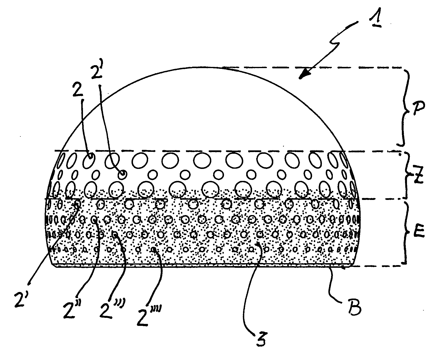
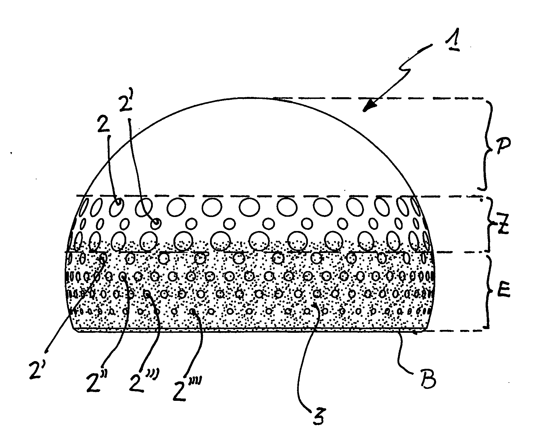
[0024]As can be seen, ball joint 1 is designed to be dome-shaped. In polar area P, the surface is perfectly smooth. This section forms the primary load-bearing part of the ball joint. The rest of the surface of ball joint 1 is characterized by a graduated structure.

[0025]An intermediate area Z follows adjacent to polar area P in the direction of the equator. Intermediate area Z is characterized by a macrostructure formed by depressions 2 and 2′. As can be seen, larger depressions 2 alternate with smaller depressions 2′; they are positioned in an alternating manner. Depressions 2 and 2′ serve primarily to hold a reservoir for the synovial fluid.

[0026]Intermediate area Z is followed by an adjacent area E approximately below the equator. Area E is characterized, on the one hand, by macroscopic depressions with hole widths between 0.5 mm and 1.2 mm. These are also used as reservoirs for the synovial fluid. However, the smaller they become, the more they are used for cleaning the synovia...


PUM


Abstract

A ball joint or cap for an artificial hip joint is described that is suitable for carrying out a rotating or pivoting motion in an artificial hip joint socket, with a gap being provided for a natural fluid film (synovial fluid) between itself and the artificial hip joint socket, and with regular depressions without interconnecting channels between them being recessed in areas of its surface. It is proposed that its surface in the polar area is smooth and without depressions, that an area is provided in an intermediate area between the smooth polar area and its equator, in which depressions are recessed with hole widths between 1.0 mm to 3.0 mm, that adjacently in the intermediate area in the direction of its base edge, further depressions are recessed, the hole widths of which become steadily smaller, the closer they lie to the base edge, with hole widths between 0.5 mm and 1.0 mm.

Description

BACKGROUND OF THE INVENTION[0001]1. Field of the Invention[0002]The present invention relates to a ball joint or cap implant for an artificial hip joint that is suited to carry out a rotating or pivoting motion in an artificial hip joint socket, with a gap being provided for a natural fluid film, the synovial fluid, between the ball joint or cap implant and the artificial hip joint socket, and with regular depressions, without interconnecting channels between them, being recessed in areas of its surface.[0003]2. Description of Related Art[0004]A ball joint of this type is known from DE 103 18 374 B3.[0005]A fundamental problem in artificial hip joints is the friction between the components of the joint, the ball joint and hip joint sockets, which leads in turn to wear and tear that can give rise to medical complications.[0006]The invention of the previously cited document was based on the effort to develop a ball joint or cap in such a way as to achieve a minimization of friction an...

Claims


Application Information

Patent Timeline
IPC IPC(8): A61F2/36
CPCA61F2/30771A61F2250/0039A61F2/3609A61F2002/30322A61F2002/30327A61F2002/30673A61F2002/30685A61F2002/30686A61F2002/3081A61F2002/30838A61F2002/30937A61F2002/3097A61F2002/3617A61F2250/0026A61F2/3601A61F2002/30652
Inventor GRUNDEI, HANS
Owner ORTHODYNAMICS GMBH
Why Eureka
Try Eureka