Error detection method and apparatus

a technology of error correction and detection method, applied in the direction of instruments, coding, code conversion, etc., can solve the problems of inability to achieve standard techniques, complex error correction, and inability to always be the cas

Active Publication Date: 2009-04-30
HEWLETT-PACKARD ENTERPRISE DEV LP
View PDF7 Cites 54 Cited by
  • Summary
  • Abstract
  • Description
  • Claims
  • Application Information

AI Technical Summary

Benefits of technology

[0029]identifying a predetermined pattern of errored sum nodes in the logical network thereby to identify one or more associated errored data-set bits.

Problems solved by technology

However, error correction of the data passed over the quantum signal channel cannot be effected using standard techniques such as the encoding / decoding of the data using linear block codes because only a small percentage of the transmitted photons are ever received.
While the presence of one or more errors in the received word r can be easily determined by checking whether the error syndrome s is non-zero, error correction is more complicated.
However, this need not always be the case.

Method used


Image

  • Error detection method and apparatus
  • Error detection method and apparatus
  • Error detection method and apparatus

Examples


Embodiment Construction

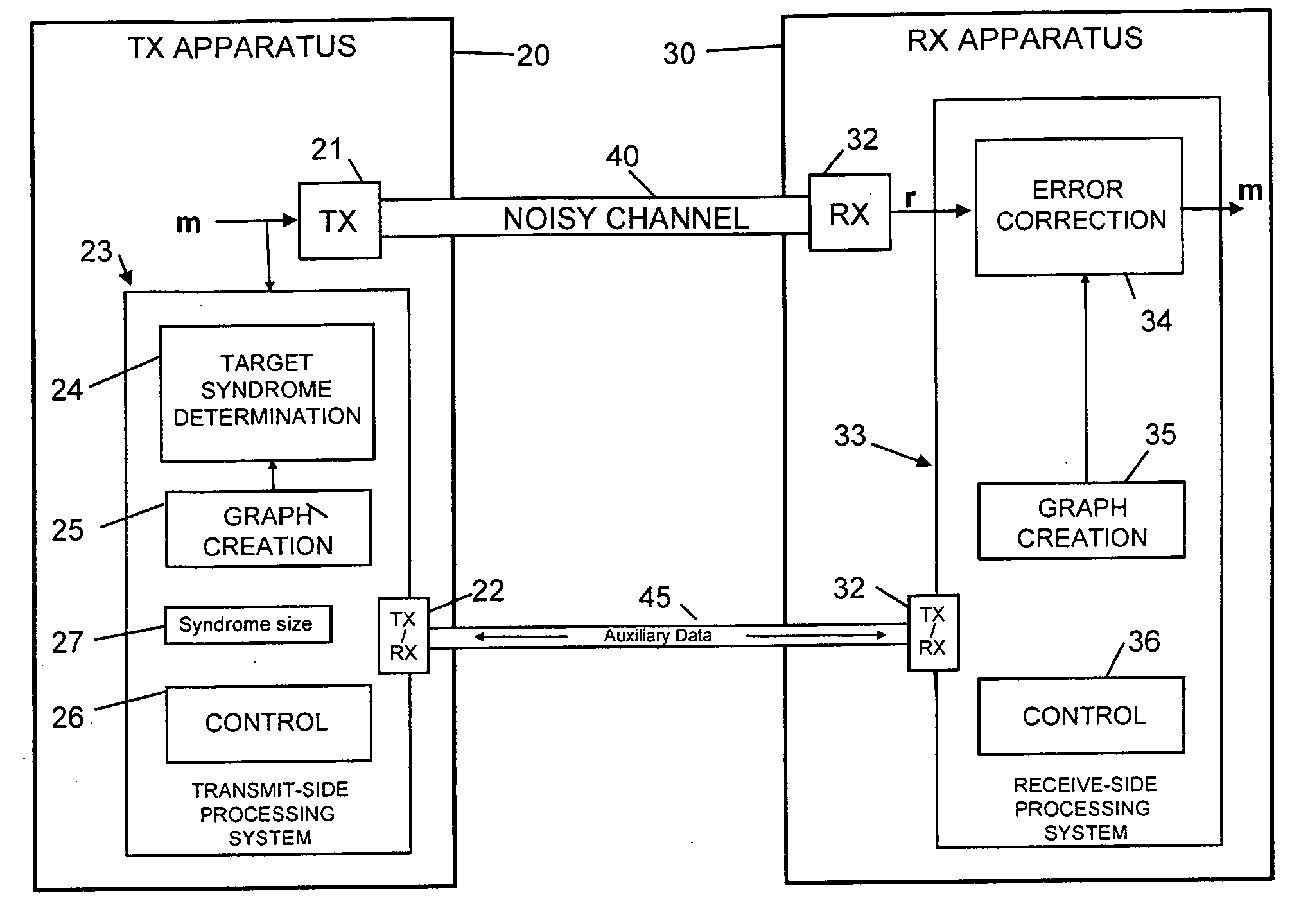
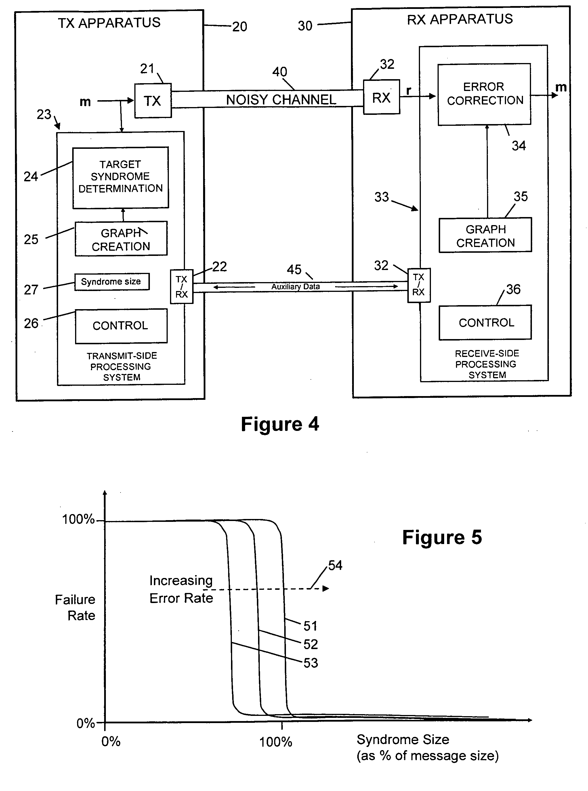
[0057]Embodiments of the present invention are initially described below with reference to a generalized context depicted in FIG. 4; application to the specific context of quantum key distribution is described later with reference to FIGS. 26 and 27.

[0058]FIG. 4 depicts a system in which subject data (a binary data set herein represented by row vector m) is sent by a first transmitter 21 of transmitting apparatus 20 over a noisy first channel 40 to a first receiver 32 of receiving apparatus 30, the output of the first receiver 32 being errored received data (a binary data set herein represented by row vector r). Use of the row vectors m and r to represent the subject data and received data is for convenience and is not to be taken to imply that the first channel 40 is a bit-serial channel though this will often be the case.

[0059]A transmit-side processing system 23 cooperates with a receive-side processing system 33 to enable an error correction block 34 of the receive-side processi...


PUM


Abstract

To identify errored bits in a binary data set, an ordered plurality of modulo-2 summations of respective selections of the data-set bits are compared with a target syndrome. The selections of data-set bits are defined by the connection of sum nodes to variable nodes in a logical network of nodes and edges where each variable node is associated with a respective data-set bit and each sum node corresponds to a respective modulo-2 summation. Any sum node for which the corresponding summation of selected data-set bits is found to be inconsistent with the target syndrome is identified as errored. Predetermined patterns of errored sum nodes are then looked for to identify one or more associated errored data-set bits. The identified errored data-set bits can then be flipped to correct them

Description

CROSS-REFERENCE TO RELATED APPLICATION[0001]This application claims priority from GB Application No. 0721310.1, filed Oct. 31, 2007.FIELD OF THE INVENTION[0002]The present invention relates to methods and apparatus for detecting, and preferably correcting, errored bits in binary data sent over a noisy channel and is of particular, but not exclusive, relevance to quantum key distribution (QKD) methods and apparatus.BACKGROUND TO THE INVENTION[0003]QKD methods and systems have been developed which enable two parties to share random data in a way that has a very high probability of detecting any eavesdroppers. This means that if no eavesdroppers are detected, the parties can have a high degree of confidence that the shared random data is secret. QKD methods and systems are described, for example, in U.S. Pat. No. 5,515,438, U.S. Pat. No. 5,999,285 and GB 2427317 A. In many known QKD systems, for example BB84 free-space systems, randomly polarized photons are sent from a transmitting ap...

Claims


Application Information

Patent Timeline
Patent Type & Authority Applications(United States)
IPC IPC(8): G06F11/00
CPCH03M13/1108H03M13/1111H04L9/0858H04L9/0662H03M13/37H03M13/13H03M13/35H04L1/005H04L9/0852
Inventor HARRISON, KEITHMUNRO, WILLIAM
Owner HEWLETT-PACKARD ENTERPRISE DEV LP
Why Eureka
Try Eureka