Suction Filter for an Automatic Transmission

a technology for automatic transmissions and suction filters, applied in the direction of gearing details, filtration separation, separation processes, etc., can solve the problems of allowing large contaminants to reenter and recirculate through the transmission, adversely affecting the pump prime, and excessively long periods, so as to avoid the instability of the bypass valve and minimize the length of time

Active Publication Date: 2009-05-07
FORD GLOBAL TECH LLC
View PDF7 Cites 13 Cited by
  • Summary
  • Abstract
  • Description
  • Claims
  • Application Information

AI Technical Summary

Benefits of technology

[0011]When valve is open during cold temperature operation, air that accumulates in the valve passes along the channel in small, dispersed bubbles and enters the pump intake, thereby avoiding bypass valve instability due to fluctuations in pump suction flow and loss of pump prime.
[0012]To minimize the length of time that the bypass valve is opened during periods when the ATF temperature is low, the valve is located immediately adjacent the inlet 18, where the valve is most exposed to relatively warm ATF flow returning to the oil pump. The valve housing is rounded at its end to create an unrestricted flow path that promotes flow of fluid toward the valve and filter housing inlet.

Problems solved by technology

When the valve is open, however, the filter is bypassed, thereby potentially allowing large contaminants to reenter and recirculate through the transmission.
During cold temperature operation when the valve is open, air may enter the filter assembly and accumulate in large bubbles, which exit the filter and enter the intake of the pump, thereby causing slug-like fluid flow or spikes, which can produce pressure instability downstream of the pump and adversely affect the pump prime.
Undesired high pressure differential across the valve, caused by cold temperature operation and restrictions in the flow path leading to the valve inlet, may cause excessively long periods when the bypass valve is open and the filter is inoperative.

Method used


Image

  • Suction Filter for an Automatic Transmission
  • Suction Filter for an Automatic Transmission
  • Suction Filter for an Automatic Transmission

Examples


Embodiment Construction

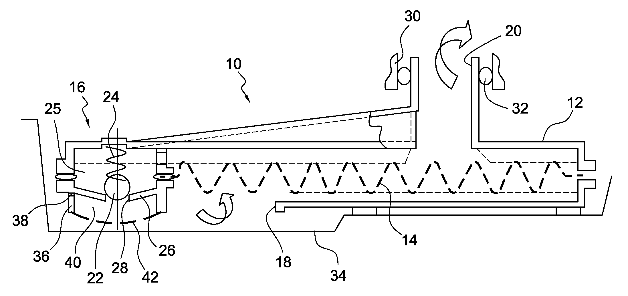
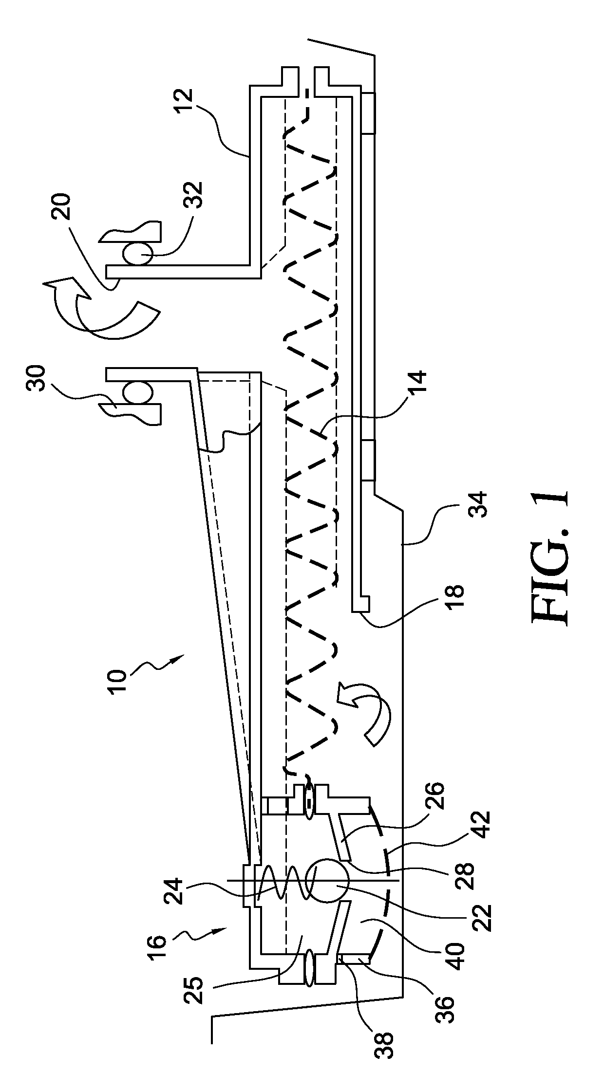
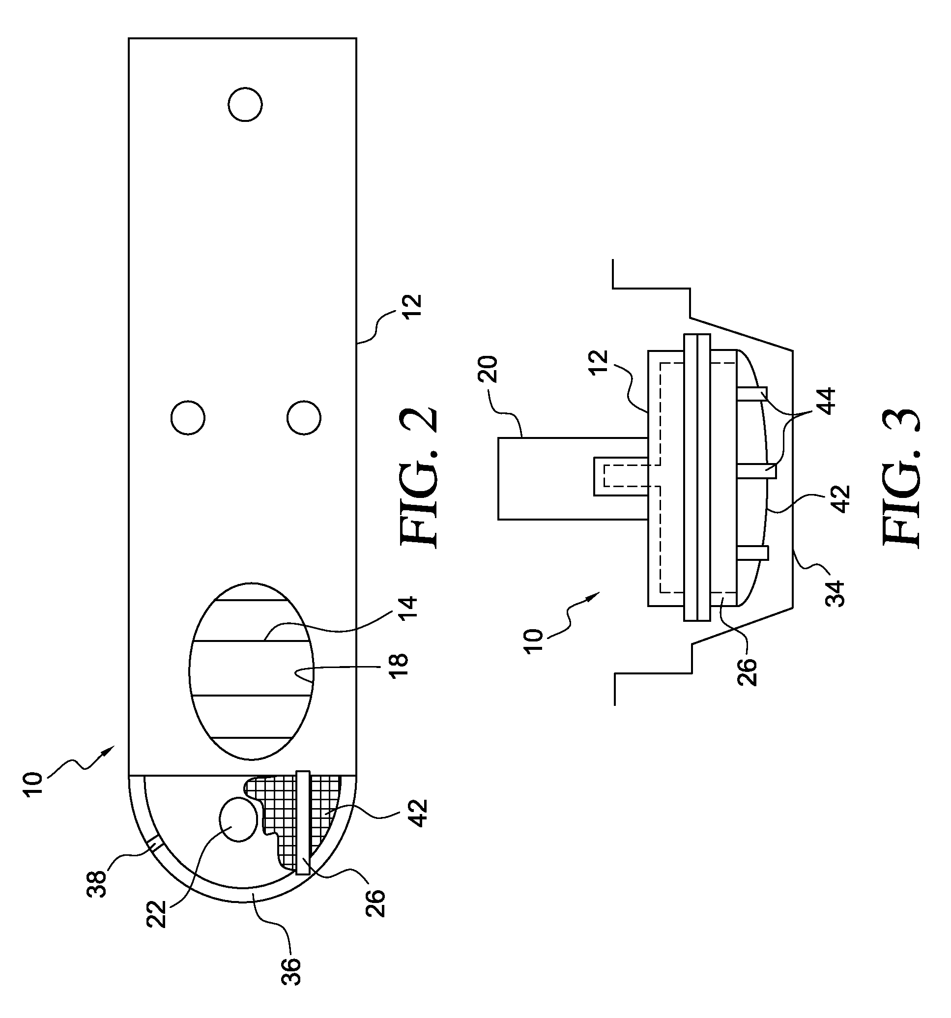
[0019]The suction filter assembly 10 shown in FIG. 1 includes a filter housing 12, filtration media 14 and pressure bypass valve 16. Filtration media 14 is directly molded to filter housing 12 and separates a housing inlet 18 and a housing outlet 20 so that all of the ATF i.e., transmission fluid, that enters though through the inlet also passes through media 14 and outlet 20 when valve 16 is closed. Filtration media 14 is able to filter small particulate matter entrained in the ATF.

[0020]The pressure bypass valve 16 is a normally-closed check valve having a ball 22 that is biased by a spring 24 toward contact with a seat 26, formed with an orifice 28. Ball 22 and spring 24 are located in a valve chamber located at a higher elevation than seat 26. Valve 16 closes when ball 22 contacts seat 26. Valve 16 opens when ball 22 moves upward out of contact with seat 26 against the force of spring 24 due to differential fluid pressure across the valve.

[0021]Filter outlet 20 is located in the...


PUM

PropertyMeasurementUnit
differential pressureaaaaaaaaaa
lengthaaaaaaaaaa
depthaaaaaaaaaa

Abstract

A filter assembly includes a filter housing including an inlet, through which hydraulic fluid enters the housing, and an outlet, through which hydraulic fluid exits the housing, valve housing containing a bypass valve located adjacent the inlet in a chamber, the valve including an orifice that opens and closes in response to differential pressure across the valve, and a screen secured to the valve housing and covering the orifice, the screen having a fine mess for removing contaminants from the fluid that flows through the valve.

Description

BACKGROUND OF THE INVENTION[0001]1. Field of the Invention[0002]This invention relates generally to a filter assembly and, in particular, to a filter for removing contaminants in automatic transmission fluid (ATF) contained in an oil pan.[0003]2. Description of the Prior Art[0004]Hydraulic fluid, which circulates continuously through an automatic transmission and an external oil cooler, reenters a transmission oil pan from the cooler through a filter, whose purpose is to remove contaminants entrained in the fluid. A hydraulic pump is supplied with fluid from the outlet of the filter. A bypass valve may be arranged in parallel flow path with a filter element such that the valve opens and closes in response to differential pressure across the valve.[0005]When the valve is open, however, the filter is bypassed, thereby potentially allowing large contaminants to reenter and recirculate through the transmission.[0006]During cold temperature operation when the valve is open, air may enter...

Claims


Application Information

Patent Timeline
Patent Type & Authority Applications(United States)
IPC IPC(8): B01D35/147F16H57/04
CPCB01D35/0273F16H57/0404F16H57/0452B01D35/147
Inventor PEKARSKY, LEVDROSTE, TIMOTHY A.HAFEMEISTER, GARY H.
Owner FORD GLOBAL TECH LLC
Why Eureka
Try Eureka