Air vent valve for beverage makers

a beverage maker and air vent valve technology, applied in the field of commercial and consumer products, can solve the problems of air vent valves that are not reliable enough to meet stringent quality standards, floats may also not be able to seal properly, and wet carpet conditions in aircraft, so as to reduce the range of movement of the ball, and eliminate the effect of chattering

Inactive Publication Date: 2010-06-03
BE INTPROP
View PDF47 Cites 12 Cited by
  • Summary
  • Abstract
  • Description
  • Claims
  • Application Information

AI Technical Summary

Benefits of technology

[0014]One important advantage of the invention is the elimination of chattering. Based on the theoretical and experimental findings, the vent opening and the ball weight are critical to robust (and chatter-free) performance. The invention recognizes that to assure robust performance, the flow through the vent opening must be high so that the system dynamics are outside the range of oscillatory (chattering) zone. This is achieved by keeping proper vent hole size in relation to the rest of parameters such as float weight that affect system dynamics.
[0015]Another aspect of the invention is the minimization of the length of time for the air vent valve to open or close. This is achieved by adjusting the weight of the float in relation to the vent hole size and expected operating pressure range of the main tank that supplies water to the tank assembly of the beverage maker. In addition, by minimizing the range of movement of the ball, the ball is quickly able to shut the vent hole during the filling operation. The collar allows optimizing the ball size and indirectly therefore the weight by controlling the size of passage within which the ball is restricted to move, which has direct bearing on the time to shut the vent hole. This way, the outside body of the valve can still be kept in line with torque forces that are typically encountered during assembly or maintenance operations.
[0016]Another advantage of the invention is the elimination of leaks. This design has been found to be completely leak-proof, by minimizing the time to shut the vent hole. The design utilizes a spherical float to minimize the possibility of misalignment of the float with the seat. Also, by keeping the contact area low, it naturally prevents sticking.
[0017]Another advantage of the invention is the improvement of the useful life of the air vent valve by eliminating factors that lead to failures. For example, depending on the quality of water there can be significant amount of scale build-up. A collar made of a smooth, corrosion resistant material adds to the reliability of the valve by not allowing salt deposition, which particularly becomes worse once there is corrosion due to roughness of the surface. This salt deposition can otherwise affect the movement of the float, and hence lead to unreliable sealing that can result in leaks.
[0018]Another advantage of the invention is the minimization of wear and tear of components during the lifetime of the air vent valve assembly. This is accomplished by eliminating chattering, and by providing a soft sealing surface against which the float impinges in the course of its operation. The surface of the ball thereby remains smooth, and is therefore not susceptible to leaking or salt deposition.
[0019]Other features and advantages of the present invention will become more apparent from the following detailed description of the preferred embodiments in conjunction with the accompanying drawings, which illustrate, by way of example, the operation of the invention.

Problems solved by technology

Air vent valves are typically used in aircraft beverage makers in conjunction with filling and draining a fresh water tank assembly, but in the past such air vent valves frequently have not been as reliable as desired to meet stringent quality standards.
These floats are susceptible to wear and tear (typically pitting due to mechanical pounding particularly compounded by chattering and cracking) which then results in a leak, because the body surface of the float is no longer smooth enough to seat properly against the vent hole.
Floats may also not be able to seal properly due to wear and tear of the seat against which the float seals, because of high impact to the valve seat after some usage, from a variety of factors.
This causes leaks which, depending on the galley configuration, can be sufficient to cause a wet carpet condition in the aircraft, which is clearly not desirable.
Also, a float can at times become stuck in a seated position in an air vent valve, which prevents drainage of liquid from the beverage maker, resulting in an inoperative condition.
A common complaint from the customers is that such beverage makers for aerospace application become inoperative due to failure of an air vent valve, since having a beverage maker out of service due to a relatively inexpensive component is very expensive for an airline.
Another major disadvantage of some conventional air vent valves is that the valves can vibrate or chatter in an audible manner in the operating pressure range of the tank on an aircraft.
This chatter is not only annoying, but is usually also sufficiently prolonged to cause continuous leaks during that time.
The chattering and vibration shortens useful life of the vent valve, lowering customer satisfaction and causing higher warranty costs.

Method used


Image

  • Air vent valve for beverage makers
  • Air vent valve for beverage makers
  • Air vent valve for beverage makers

Examples


Embodiment Construction

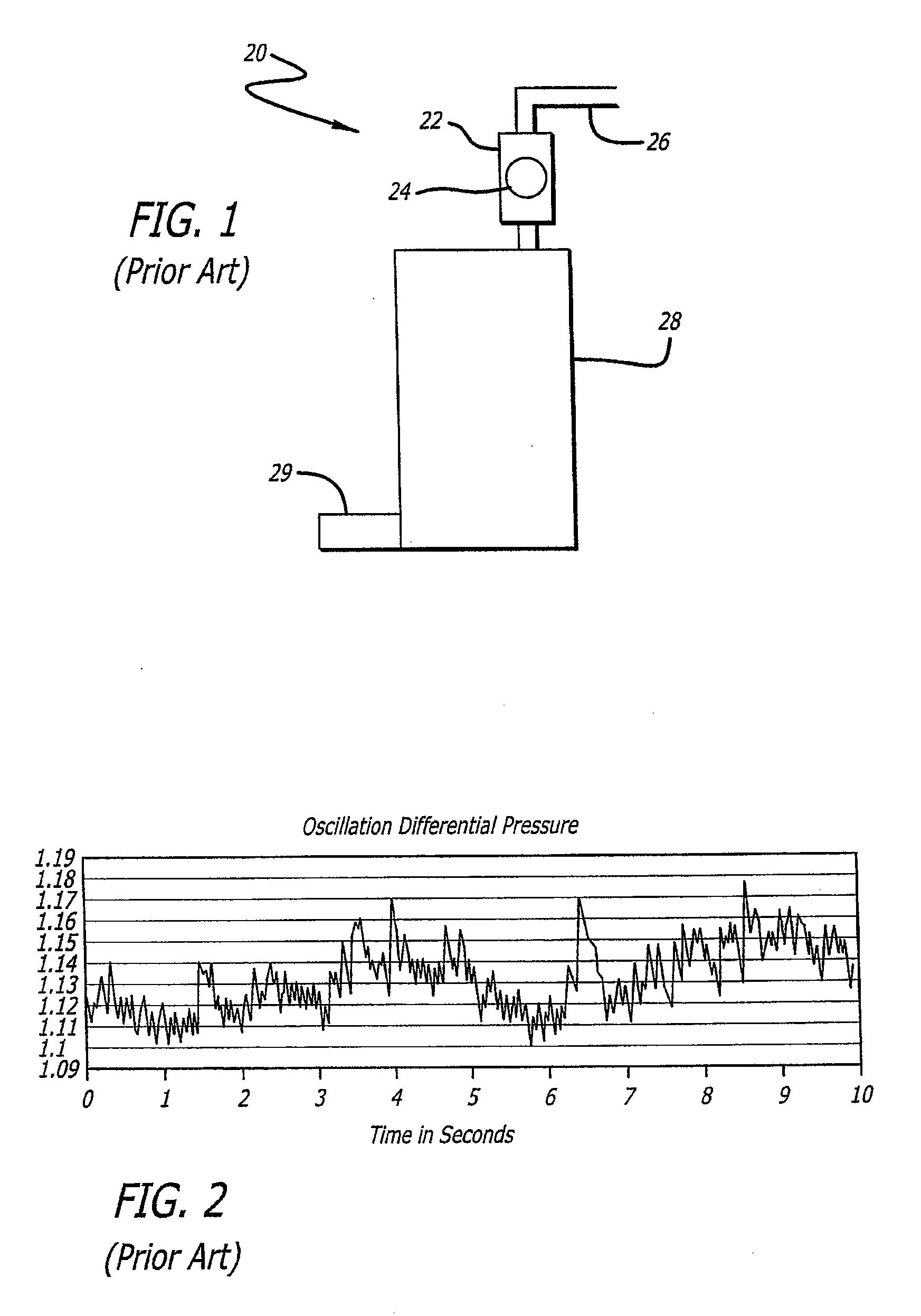
[0046]Referring to FIG. 1 illustrating a schematic diagram of a prior art beverage maker vent valve, a vent valve assembly or fluid flow element (FFE) 20 includes a valve body 22 housing a float or valve element (VE) 24, controlling fluid flow to and from the vent outlet 26 from the water tank, or chamber, or fluid volume element (FVE) 28, which receives water through the water inlet 29. From a system dynamics point of view, the elements that describe the essential elements of the system are the fluid flow element (FFE) 20, the fluid volume element (FVE) 28, and the valve element (VE) 24.

[0047]The change in rate of flow of fluid with time (t) across the fluid flow element is governed by the equation (1) below.

dφ / dt=(A / L)(Pin−Pout−Ploss−Phead) / ρ  (1)

[0048]Where,

φ=Flow rate, A=Cross sectional area of flow path, L=Length of flow path

Pin=Inlet pressure, Pout=Outlet pressure, Ploss=Pressure loss due to friction and bends etc

Phead=Head pressure loss between upstream and downstream points

ρ...


PUM


Abstract

The air vent valve includes a vent valve body and a valve adapter that sealingly mate together. A vent outlet of the vent valve body and a fluid inlet of the valve adapter are connected through interior flow chambers of the vent valve body and valve adapter. A spherical ball float is constrained for longitudinal movement within a tubular collar in the interior chamber of the vent valve body, and a planar valve seat member with a central flow aperture is disposed within the vent valve body between the tubular collar and the outflow passage of the vent valve body.

Description

CROSS-REFERENCES TO RELATED APPLICATIONS[0001]This divisional application is based upon and claims the benefit of priority from the prior U.S. patent application Ser. No. 11 / 407,341, filed Apr. 19, 2006, and U.S. Provisional Patent Application Ser. No. 60 / 673,538, filed Apr. 20, 2005, the entire contents of which are incorporated herein by reference.BACKGROUND OF THE INVENTION[0002]The invention generally relates to commercial and consumer products related to venting and draining of containers, and more particularly relates to venting and draining of beverage makers for aerospace applications. The invention is specifically suitable for applications that typically handle fluids and depend on a mechanical or electrical means to ensure reliable venting of air into or out of a container, such as a tank assembly in the case of a beverage maker.[0003]Air vent valves are typically used in aircraft beverage makers in conjunction with filling and draining a fresh water tank assembly, but in ...

Claims


Application Information

Patent Timeline
Patent Type & Authority Applications(United States)
IPC IPC(8): F16K24/04
CPCF16K27/0245F16K24/046Y10T137/3099
Inventor KSHIRSAGAR, GIRISH S.VED, DHARMESH A.ELLISON, JOHN ERICKFLIESS, WINSTONWEISS, DAVIDYODER, NATHANIEL F.
Owner BE INTPROP
Why Eureka
Try Eureka