Flow rate sensor system and method for non-invasively measuring the flow rate of a bodily fluid

a flow rate sensor and flow rate technology, applied in temperature sensors, intracranial pressure measurement, medical science, etc., can solve the problems of inability to provide quantitative flow rate measurement, inability to demonstrate in humans the capability of providing reliable and accurate quantitative information on shunt function, and common shunt failure, etc., to achieve sufficient inductive coupling and minimize the length of time

Inactive Publication Date: 2015-10-22
VIVONICS
View PDF9 Cites 5 Cited by
  • Summary
  • Abstract
  • Description
  • Claims
  • Application Information

AI Technical Summary

Benefits of technology

[0023]In one embodiment, the method may include thermally isolating the heating element and the temperature sensor. The method may further include locating the encapsulated implant using data wirelessly sent from the encapsulated implant to the external device. The method may further include positioning an external coil of the external device proximate and in alignment with an implant coil of the encapsulated implant to provide sufficient inductive coupling between an external coil of the external device and an implant coil. The method may include storing on a microcontroller of the encapsulated implant the set of previously obtained calibration measurements of heat dissipation. The method may include storing on a microcontroller of the encapsulated implant identification information associated with the encapsulated implant. The method may include determining the flow rate from a current measured temperature rise up when the temperature of the heating element is determined to be no longer rising to minimize the length of time needed to determine the flow rate, the amount of heat generated by the heating device, and the amount of heat delivered to a patient.

Problems solved by technology

However, shunt failure is common and shunt revision surgery is even more common than initial placement.
The ShuntCheck has the advantage that it is not implanted, but it has the disadvantage that it is unable to provide a quantitative measure of flow rate.
However, none of the devices discussed above have yet to be demonstrated in humans to provide sufficiently reliable and accurate quantitative information on shunt function to be adopted for clinical use.
Such techniques require relatively expensive equipment typically only available in hospitals.
Additionally, the progression of disease and injuries cannot be studied extensively because of the lack of shunt flow data.

Method used


Image

  • Flow rate sensor system and method for non-invasively measuring the flow rate of a bodily fluid
  • Flow rate sensor system and method for non-invasively measuring the flow rate of a bodily fluid
  • Flow rate sensor system and method for non-invasively measuring the flow rate of a bodily fluid

Examples


Embodiment Construction

[0050]Aside from the preferred embodiment or embodiments disclosed below, this invention is capable of other embodiments and of being practiced or being carried out in various ways. Thus, it is to be understood that the invention is not limited in its application to the details of construction and the arrangements of components set forth in the following description or illustrated in the drawings. If only one embodiment is described herein, the claims hereof are not to be limited to that embodiment. Moreover, the claims hereof are not to be read restrictively unless there is clear and convincing evidence manifesting a certain exclusion, restriction, or disclaimer.

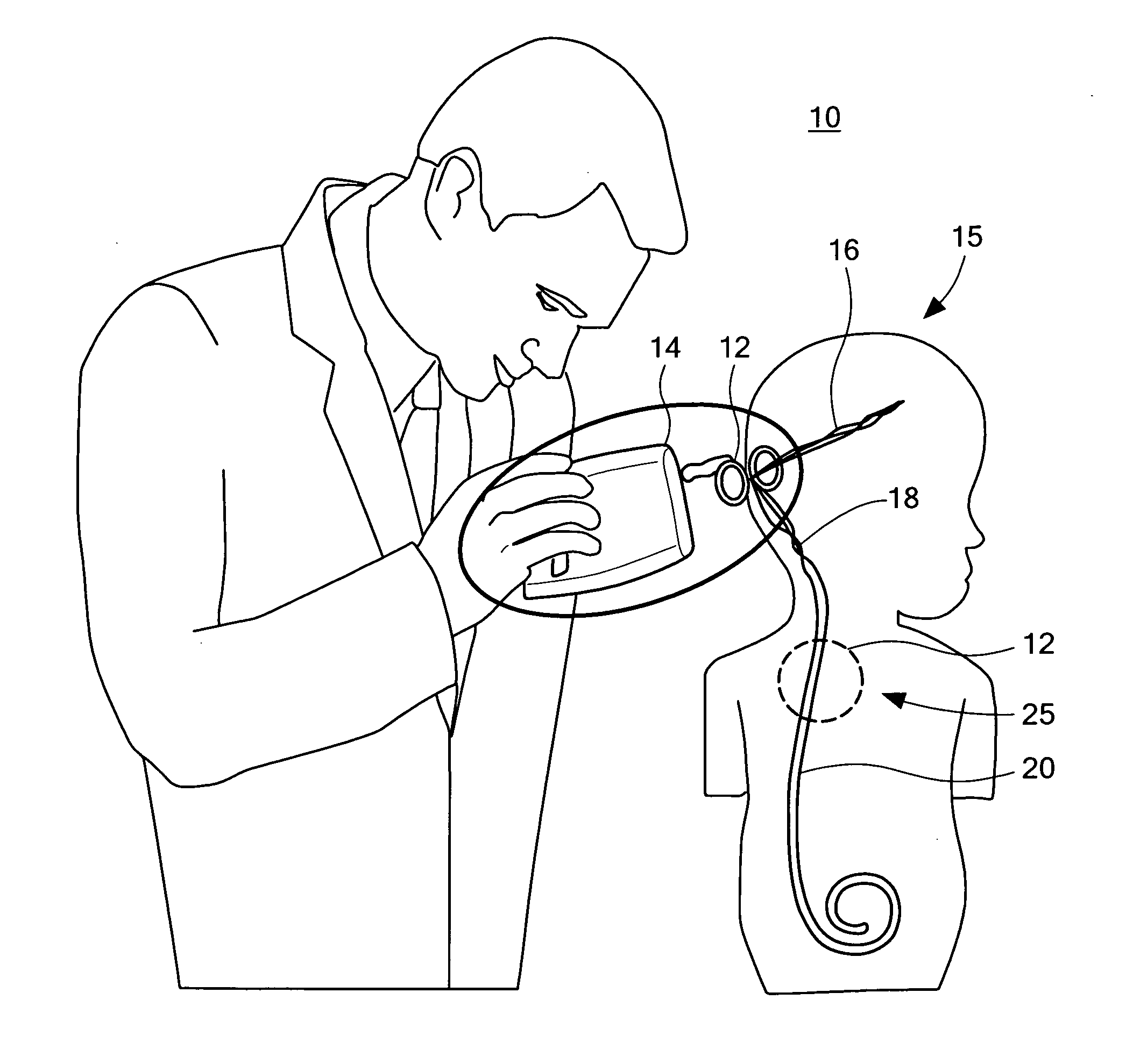
[0051]There is shown in FIG. 1 one embodiment of system 10 and the method thereof for non-invasively measuring the flow rate of a bodily fluid. System 10 includes encapsulated implant 12 and external device 14. In the example shown in FIG. 1, encapsulated implant 12 is implanted into human body 15 and is coupled to ventricu...


PUM


Abstract

A flow rate sensor system for non-invasively measuring the flow rate of a bodily fluid. The system includes an encapsulated implant having a flow tube having an inlet and an outlet configured to receive a flow of a bodily fluid. A heating element externally coupled to the flow tube is configured to dissipate heat at a predetermined rate over a predetermined amount of time. A temperature sensor externally coupled to the heating element is configured to measure a temperature rise of the heating element over the predetermined amount of time. An implant microcontroller coupled to the temperature sensor is configured to determine the flow rate of the bodily fluid in the flow tube from the measured temperature rise and a curve fit to a stored set of previously obtained calibration measurements. An implant power and communication subsystem is coupled to the implant microcontroller configured to wirelessly receive power and wirelessly transmit and receive data. The system also includes an external device having an external microcontroller and an external power and communication subsystem coupled to the external microcontroller configured to wirelessly deliver power to the implant power and communication subsystem and transmit and receive data to and from the implant power and communication subsystem.

Description

GOVERNMENT RIGHTS[0001]This invention was made with U.S. Government support under Grant No. 6R44NS056628-04 awarded by the National Institutes of Health. The Government may have certain rights in certain aspects of the subject invention.FIELD OF THE INVENTION[0002]This invention relates to a flow rate sensor system and method for measuring the flow rate of a bodily fluid.COMPUTER PROGRAM LISTING APPENDIX[0003]A computer program listing appendix is filed herewith on compact disk. The material on the compact disk is hereby incorporated by reference. Two identical compact disks have been submitted. Each compact disk contains two files entitled source implant.txt and source external.txt. The two disks were created on Mar. 21, 2014.BACKGROUND OF THE INVENTION[0004]Drainage of cerebrospinal fluid (CSF) is one major life-sustaining therapy which may be used for patients with congenital or acquired hydrocephalus or patients with serious head injuries. Ventriculo-peritoneal (VP) shunt placem...

Claims


Application Information

Patent Timeline
Patent Type & Authority Applications(United States)
IPC IPC(8): A61B5/01A61B5/00A61B5/026
CPCA61B5/01A61B5/0008A61B5/7278A61B5/026A61B5/0031A61B5/031A61B2560/0219A61B2560/0223A61B2562/0271
Inventor GOLDIE, JAMES H.TRUONG, THIEU Q.DUONG, MINHRUSSELL, THOMAS
Owner VIVONICS
Why Eureka
Try Eureka