Inductive coil assembly

a technology of inductive coils and coil assemblies, which is applied in the direction of transformer/inductance casings, gas-filled discharge tubes, and battery arrangements for several simultaneous batteries. it can solve the problems of insufficient inductive coupling, limited use of inductive power transfer, and significant limitation on the overall design and adaptability of inductively powered devices. achieve sufficient inductive coupling, facilitate manufacturing, and permit molding

Inactive Publication Date: 2005-09-01
PHILIPS IP VENTURES BV
View PDF10 Cites 19 Cited by
  • Summary
  • Abstract
  • Description
  • Claims
  • Application Information

AI Technical Summary

Benefits of technology

[0008] In one embodiment, the inductive coil assembly includes a one-piece bobbin that facilitates manufacture and assembly of the inductive coil assembly. The bobbin includes a separate spool with winding guides along each of the three axes and is designed to permit molding without the need for slides, pins or other complex mold tools.
[0009] In another embodiment, the inductive coil assembly can be used as a primary to transmit power or communication or both to a second. The inductive coil assembly with different coils at different orientations can generate magnetic fields at different orientation and thereby provide sufficient inductive coupling when an inductive device with only a single secondary coil is at different orientations.
[0010] In applications where only a single coil is used, it is possible that a device randomly placed within a magnetic field will be located with the coil oriented substantially parallel to the magnetic field. In such situations, the secondary may not receive sufficient power to power the device from the primary. The use of multiple coils addresses this problem by providing a secondary coil arrangement that significantly increases the likelihood that at least one coil will at least substantially intersect the flux lines of the magnetic field generated by the primary. For example, an inductive device may include a secondary with two coils that are oriented at 90 degrees to one another. With this configuration, at least one of the two coils is likely to extend across the flux lines of the magnetic field and receive power from the primary. The number of separate coils may vary from application to application, for example, the inductive device may include 3, 4, 6 or 8 coils at different orientations to provide improved efficiency in a wide variety of orientations. By providing a sufficient number of coils at different orientations, the inductive device can be configured to receive power from the primary regardless of the orientation of the inductive device.
[0011] The present invention provides a simple and inexpensive inductive coil assembly that improves the efficiency of inductive systems when precise primary / secondary alignment does not exist. The present invention permits power and communications to be transferred inductively in an environment where the position of the secondary within the primary may vary. The inductive coil assembly is manufactured on a bobbin that provides winding guides along all three axes, yet is easily manufactured without complex slide, pins or other complex mold tools.

Problems solved by technology

The use of inductive power transfer has, however, for the most part been limited to niche applications, such as for connections in wet environments.
The limited use of inductive power transfer has been largely the result of power transfer efficiency concerns.
The conventional practice of providing precise alignment between the primary and secondary coil has placed significant limitation on the overall design and adaptability of inductively powered devices.

Method used


Image

  • Inductive coil assembly
  • Inductive coil assembly
  • Inductive coil assembly

Examples


Embodiment Construction

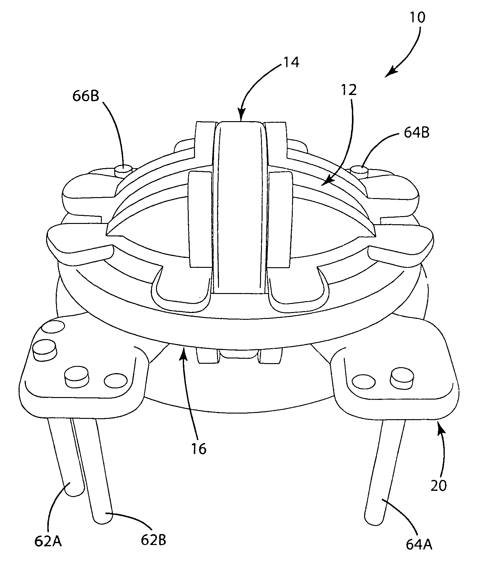
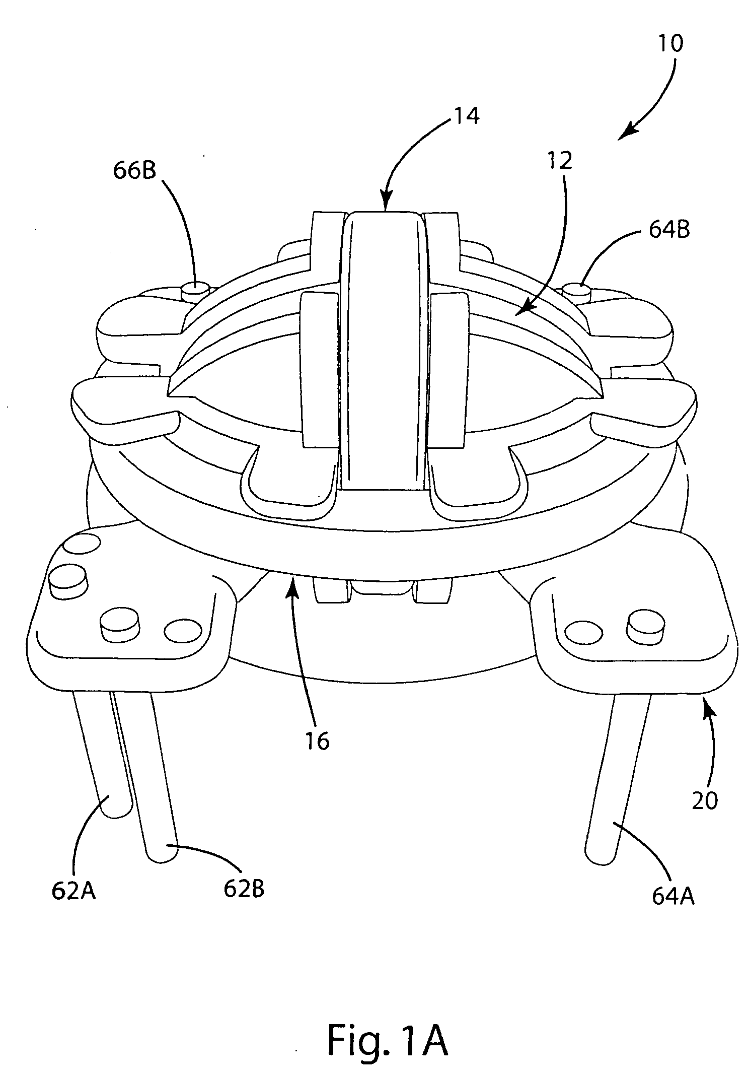
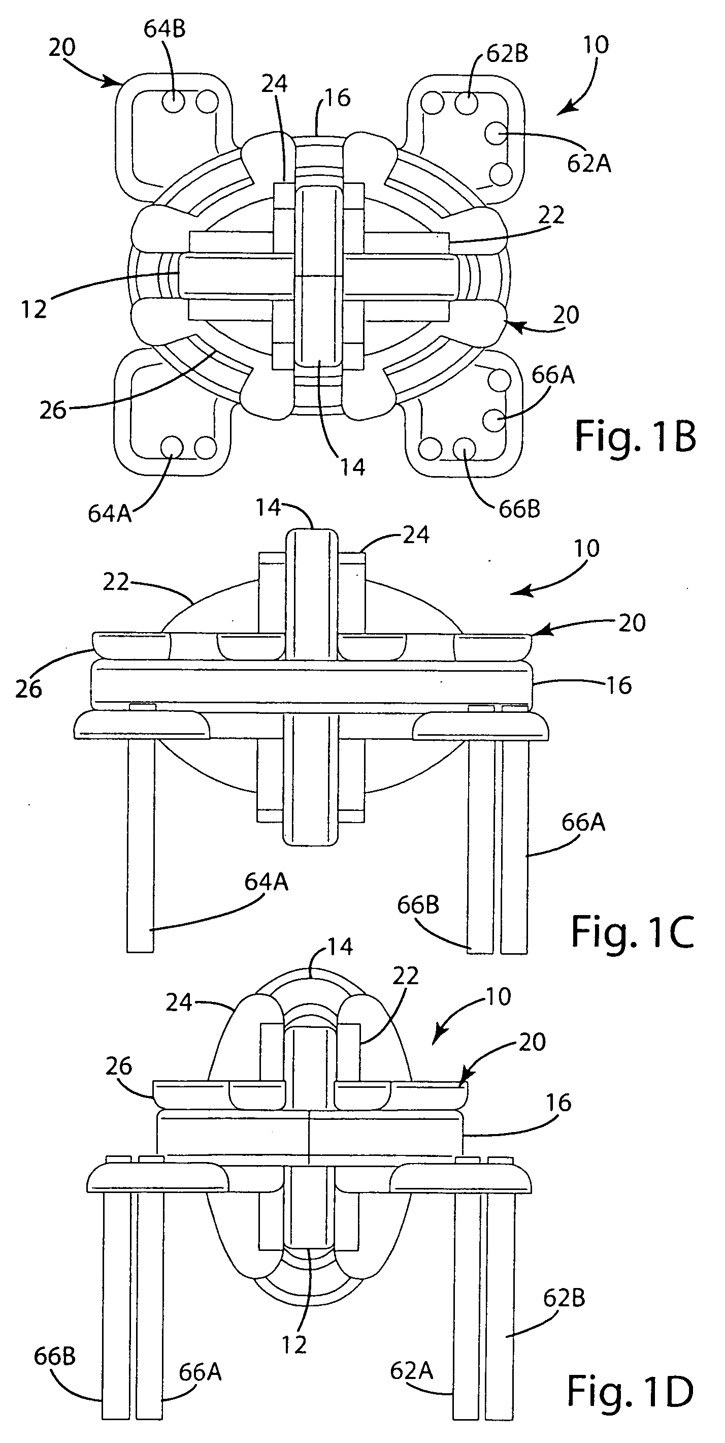
[0030] An inductive coil assembly 10 manufactured in accordance with an embodiment of the present invention is shown in FIGS. 1a-d. The inductive coil assembly 10 generally includes three separate coils 12, 14 and 16 that are arranged at separate orientations with respect to one another. The separate coils 12, 14 and 16 may be electrically connected to a device through an inductive control circuit. The separate coils 12, 14 and 16 may be wrapped around a one-piece bobbin 20 that facilitates the manufacture and assembly of the present invention. Although the present invention is described in connection with a three-coil embodiment, the number of coils may vary.

[0031] As noted above, the inductive coil assembly 10 includes a bobbin 20 for supporting the various coils 12, 14 and 16. In one embodiment, the bobbin 20 is a one-piece structure that is specially designed for easy manufacture and easy assembly of the inductive coil assembly 10. In the illustrated embodiment, the bobbin 20 i...


PUM

PropertyMeasurementUnit
angleaaaaaaaaaa
angleaaaaaaaaaa
mutual inductanceaaaaaaaaaa

Abstract

An inductive coil assembly having multiple coils arranged at distinct orientations to provide efficient inductive coupling of power or communications or both to a device when the device is arranged at different orientations with respect to the inductive primary coil. In one embodiment, the inductive coil assembly includes three coils, each oriented along one of the x, y and z axes of a standard Cartesian three-dimensional coordinate system. The three separate coils provide effective transfer of power and communication when the device is at essentially any orientation with respect to the primary coil. In an alternative embodiment, the multi-axis inductive coil assembly of the present invention can function as a primary to inductively transmit power or communication or both over a plurality of magnetic fields at distinct orientations.

Description

[0001] The present invention is a continuation-in-part of U.S. patent application Ser. No. 10 / 357,932, entitled “Inductively Powered Apparatus,” which was filed on Feb. 4, 2003.BACKGROUND OF THE INVENTION [0002] The present invention relates to the inductive transfer of power and communications, and more particularly to methods and apparatus for receiving inductively transmitted power and communications. [0003] The principles of inductive power transfer have been known for many years. As a result of mutual inductance, power is wirelessly transferred from a primary coil (or simply “primary”) in a power supply circuit to a secondary coil (or simply “secondary”) in a secondary circuit. The secondary circuit is electrically coupled with a device, such as a lamp, a motor, a battery charger or any other device powered by electricity. The wireless connection provides a number of advantages over conventional hardwired connections. A wireless connection can reduce the chance of shock and can...

Claims


Application Information

Patent Timeline
Patent Type & Authority Applications(United States)
IPC IPC(8): A61L2/10B01D17/12C02F1/00C02F1/32C02F9/00H01F5/02H01F38/14H02J7/00H02J7/02H05B37/03H05B39/00H05B41/24H05B41/36
CPCA61L2/10H05B41/36C02F1/008C02F1/325C02F9/005C02F2201/3228C02F2201/326C02F2209/005C02F2209/008C02F2209/40H01F5/02H01F38/14H01F2005/027H01F2005/043H01F2005/046H02J7/0027H02J7/025H05B37/03H05B39/00H05B41/24C02F1/001H05B47/20H02J50/402H02J50/005H02J50/12C02F9/20H01F27/28
Inventor BAARMAN, DAVID W.LAUTZENHEISER, TERRY L.
Owner PHILIPS IP VENTURES BV
Why Eureka
Try Eureka