Methods and apparatuses for filtering water from oil and gas wells

a technology of filtering apparatus and well water, which is applied in the direction of grey water treatment, water treatment multi-stage treatment, and treatment of natural treatment water, etc., can solve the problems of large space occupation, difficulty in maintaining filtering apparatus, and large area of space occupation

Inactive Publication Date: 2009-05-07
MILLER ROBERT L
View PDF90 Cites 24 Cited by
  • Summary
  • Abstract
  • Description
  • Claims
  • Application Information

AI Technical Summary

Benefits of technology

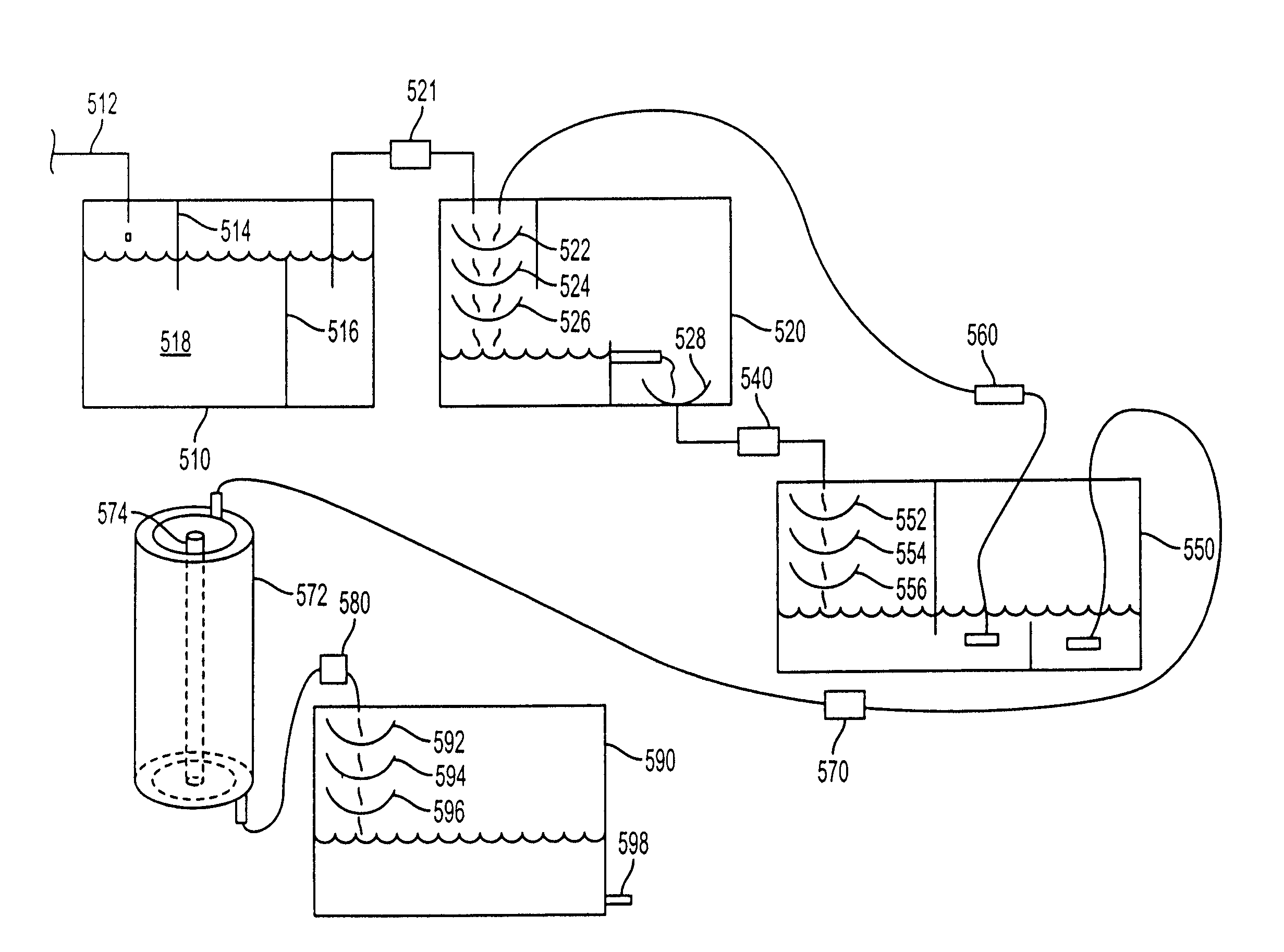
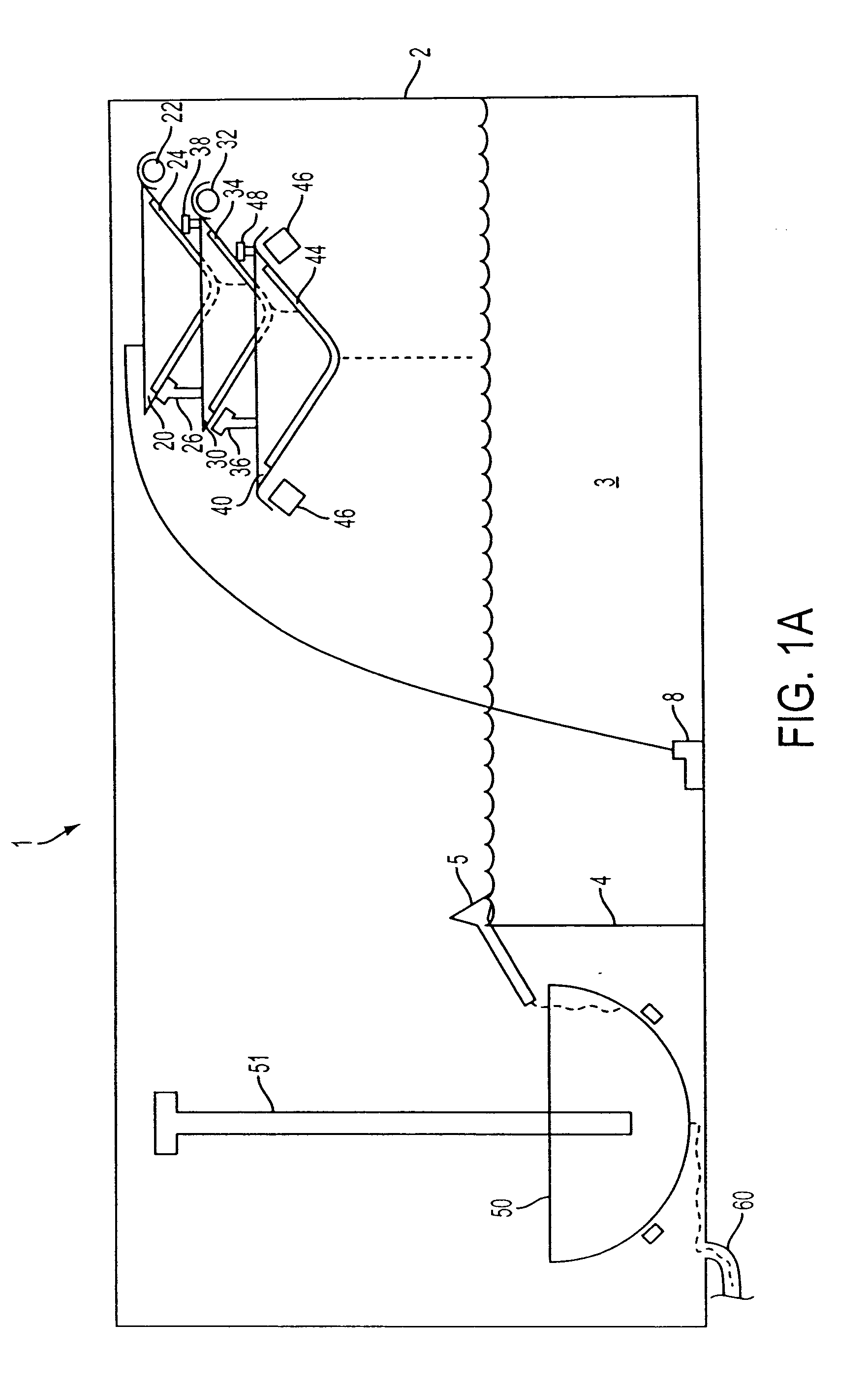
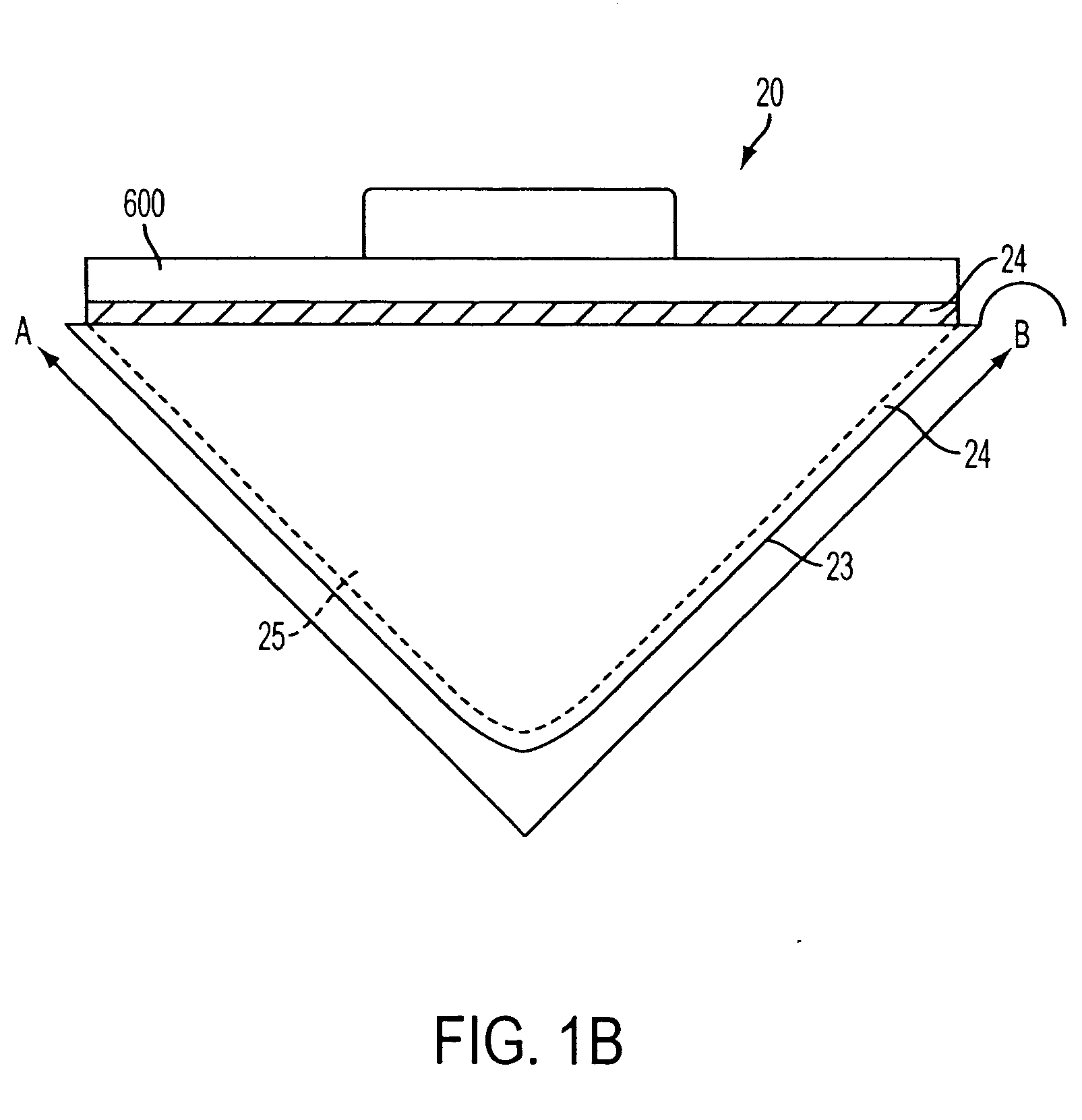
[0007]Provided is a recycling apparatus for recycling contaminated water from an oil or gas well comprising a holding vessel containing contaminated water from an oil or gas well, a main tank constructed and arranged for holding filtered oil or gas well water and having at least one opening to the environment to allow air to freely transfer between the main tank the environment; an oil-water separator in communication with the main tank; a pump constructed and arranged for transferring contaminated water from the holding vessel to the oil-water separator; a first filter assembly in gravity feed relation with the main tank, said first filter assembly having a first filter sheet; and a second filter assembly in gravity feed relation with the main tank, said second filter assembly having a second filter sheet having a filtration size of 10 microns or less, wherein said first and second filter assemblies are constructed and arranged such that during operation contaminated water is transferred to the oil-water separator where oil is separated from the water to form oil reduced water and the oil reduced water flow through the first filter assembly to form a first filtered water solution, the first filtered water solution from the first filter assembly filters through the second filter assembly to form a recycled water solution and drops into the main tank a second distance of from about 1 to about 30 inches before contacting recycled water solution in the main tank.
[0008]Also provided is a method of recycling a contaminated water solution from an oil or gas well comprising transferring contaminated water from an oil or gas well to an oil-water separator; separating oil from the contaminated water to form an oil reduced water solution; filtering the oil-reduced water solution through a first filter assembly having a first filter sheet under ambient pressure to form a first filtered water solution and allowing the first filtered water solution to flow into a second filter assembly; filtering the first filtered water solution through the second filter assembly having a second filter sheet of 10 micron or less filtration size under ambient pressure to form a recycled water solution and allowing the recycled water solution to drop a second distance into a main tank before contacting a surface of the recycled water solution being contained in the main tank, the second distance being sufficient to aerate the recycled water solution in the main tank.

Problems solved by technology

This recycling apparatus provides no visual monitoring ability except for vacuum gauges, has no pH monitoring nor automatic adjustment capability, and the location of the unit has to be in close proximity to the wash platform and the power washer.
Furthermore, the filtering apparatus is difficult to maintain, requires a large area of space and numerous extra equipment at additional cost.
Moreover, the vacuum or pressure used to force the wash solution through a filter can undesirably force dirt through filters.
However, in these systems the filtered water is not continuously filtered through the filter media and there is only one filter media.

Method used


Image

  • Methods and apparatuses for filtering water from oil and gas wells
  • Methods and apparatuses for filtering water from oil and gas wells
  • Methods and apparatuses for filtering water from oil and gas wells

Examples


examples

[0103]In the Examples, the filter media was in a sheet form ranging from 1 foot wide×1 foot long to 6 feet wide×10 feet long. A sock style filter is currently being tested by the Colorado Department of Transportation (CDOT) that slides up over the lip on the pre-sediment tank and is tied to the spreader tube attached to the pre-sediment tank. This sock style filter is much easier to replace than the tray filter. The sock style filter can be formed by overlapping the filter sheet and sealing the ends.

[0104]The filtration size of the media used ranged from about 0.01 micron (1 micron=0.000039 inches) to about 10 microns. Particular filtrations sizes used were 0.2 microns, 0.2 micron, 0.5 micron, 1 micron, 3 micron, 5 micron, and up in increments as needed. This varied in capability by as much as 25%. The micron capability is primarily determined by the weight of the cloth used and can be varied as needed.

[0105]The manner in which the different filter media's were used depended on what...


PUM

PropertyMeasurementUnit
filtration sizeaaaaaaaaaa
distanceaaaaaaaaaa
distanceaaaaaaaaaa

Abstract

The invention relates to a method and apparatus for filtering contaminated water from an oil or gas well.

Description

[0001]This application is a Continuation-in-Part of U.S. application Ser. No. 11 / 675,867, filed Feb. 16, 2007, which is a Divisional of U.S. application Ser. No. 11 / 397,681, filed Apr. 5, 2006, now U.S. Pat. No. 7,179,372, which is a Divisional of U.S. application Ser. No. 11 / 038,457, filed Jan. 21, 2005, which is a Continuation-in-Part of U.S. application Ser. No. 10 / 939,335, filed Sep. 14, 2004, now U.S. Pat. No. 7,060,189, which is a Continuation of U.S. application Ser. No. 10 / 636,808, filed Aug. 8, 2003, now U.S. Pat. No. 6,932,910, which claims priority to U.S. application Ser. Nos. 60 / 411,382, filed Sep. 18, 2002; 60 / 408,281, filed Sep. 6, 2002; 60 / 406,059, filed Aug. 27, 2002; 60 / 404,403, filed Aug. 20, 2002; and 60 / 402,526, filed Aug. 12, 2002, the complete disclosures of which are incorporated herein by reference. This application also claims priority to U.S. patent application Ser. Nos. 60 / 632,076, filed Dec. 1, 2004; 60 / 618,605, filed Oct. 15, 2004; 60 / 598,443, filed Aug...

Claims


Application Information

Patent Timeline
Patent Type & Authority Applications(United States)
IPC IPC(8): C02F1/00
CPCB01D17/0211B01D29/014C02F2303/16C02F2301/08C02F2201/008C02F2103/44C02F2103/38B01D36/02B01D2201/188C02F1/001C02F1/004C02F1/32C02F1/40C02F1/44C02F1/444C02F1/46C02F1/48C02F2101/20C02F2101/203C02F2103/001C02F2103/002C02F2103/007C02F2103/10C02F2103/18C02F2103/325B01D17/10B01D29/56B01D36/04Y02W10/37Y02A20/152
Inventor MILLER, ROBERT L.
Owner MILLER ROBERT L
Why Eureka
Try Eureka