
Traction Control Device for Vehicle

a technology for traction control and vehicles, which is applied in the direction of electric devices, braking systems, braking components, etc., can solve the problems of difficult to always smoothly suppress the slippage of the driving wheel, and achieve the effect of suppressing preventing the slippage of the driving wheel, and changing the regenerative torque of the electric motor

Active Publication Date: 2009-05-07
HONDA MOTOR CO LTD
View PDF9 Cites 28 Cited by
  • Summary
  • Abstract
  • Description
  • Claims
  • Application Information

AI Technical Summary

Benefits of technology

[0006]In view of such circumstances, an object of the present invention is to provide a traction control device capable of smoothly and quickly controlling a slippage of a driving wheel according to the road surface condition through a regenerative operation of an electric motor coupled to the driving wheel.
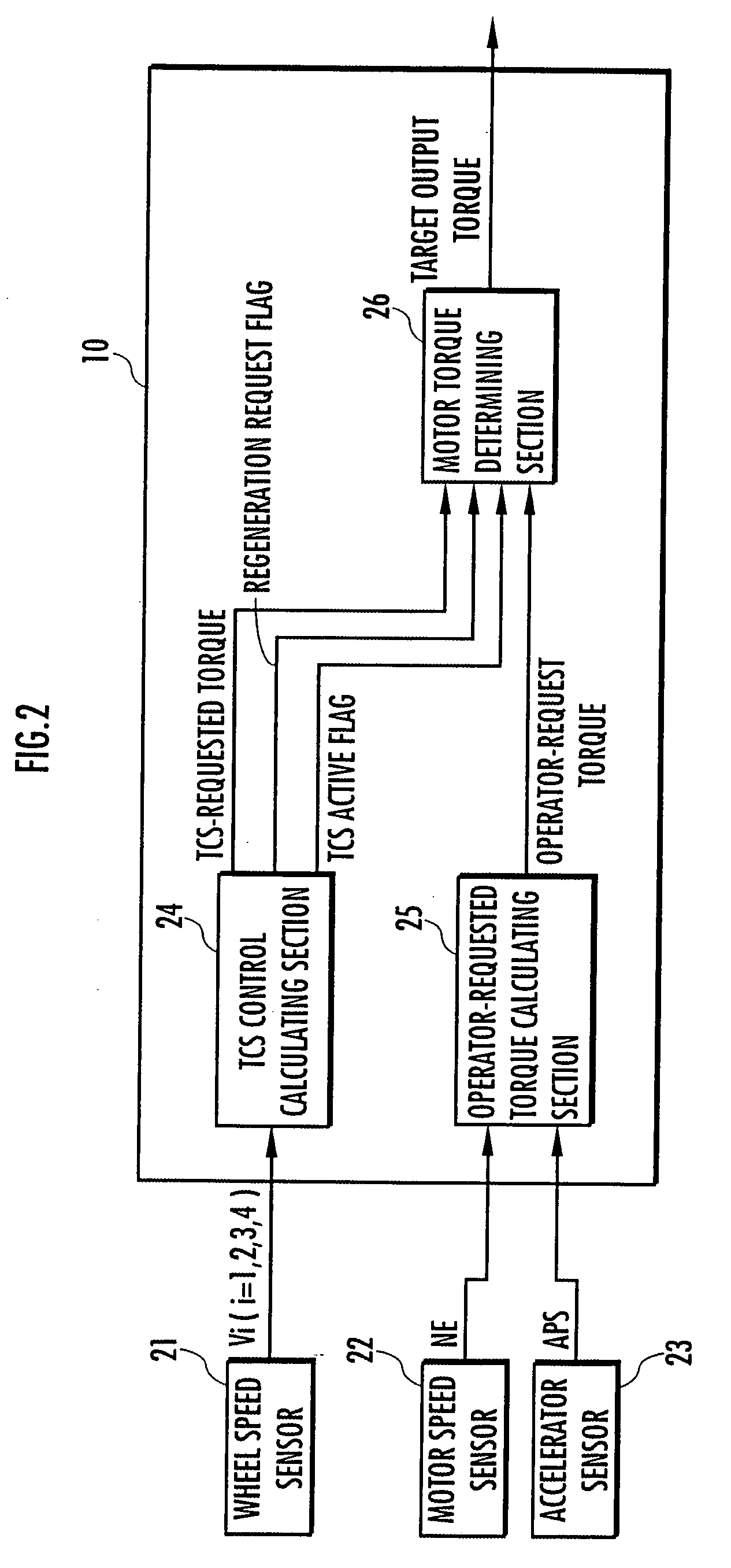
[0027]In this case, the difference between the operator-requested torque and the requested torque for traction control (the operator-requested torque minus the requested torque for traction control) increases as the operator-requested torque increases or the road surface becomes more slippery (that is, the requested torque for traction control decreases). Thus, for example, by controlling the electric motor in such a manner that the regenerative torque of the electric motor increases as the difference described above increases, the slippage of the driving wheel can be suppressed according to the manipulation of the accelerator by the operator and the road surface condition. Even if the road surface is slippery, if the amount of manipulation of the accelerator immediately before the slippage of the driving wheel occurs is relatively small, the regenerative torque at the start of the regenerative operation of the electric motor can be reduced compared with the case where the amount of manipulation of the accelerator is large. Thus, the possibility that the torque produced by the electric motor abruptly changes from the driving torque to a high regenerative torque can be reduced, and the load on the electric motor can be reduced.

Problems solved by technology

As described above, if the electric motor produces a constant regenerative torque when the slippage of the driving wheel occurs, the regenerative torque becomes excessive or insufficient depending on the road surface condition, and thus, it is difficult to always smoothly suppress the slippage of the driving wheel.

Method used


Image

  • Traction Control Device for Vehicle
  • Traction Control Device for Vehicle
  • Traction Control Device for Vehicle

Examples


first embodiment

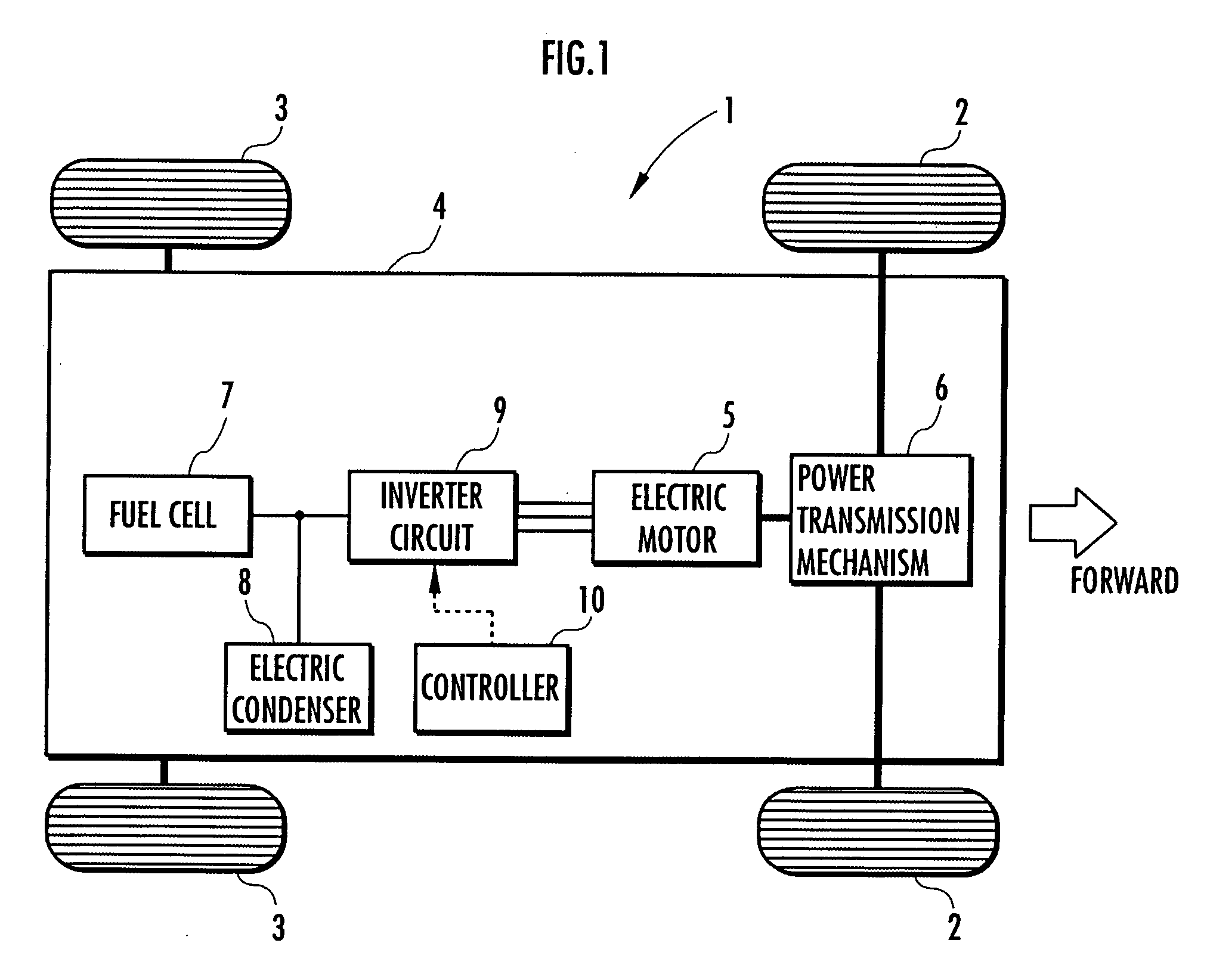
[0050]the present invention will be described with reference to FIGS. 1 to 8.

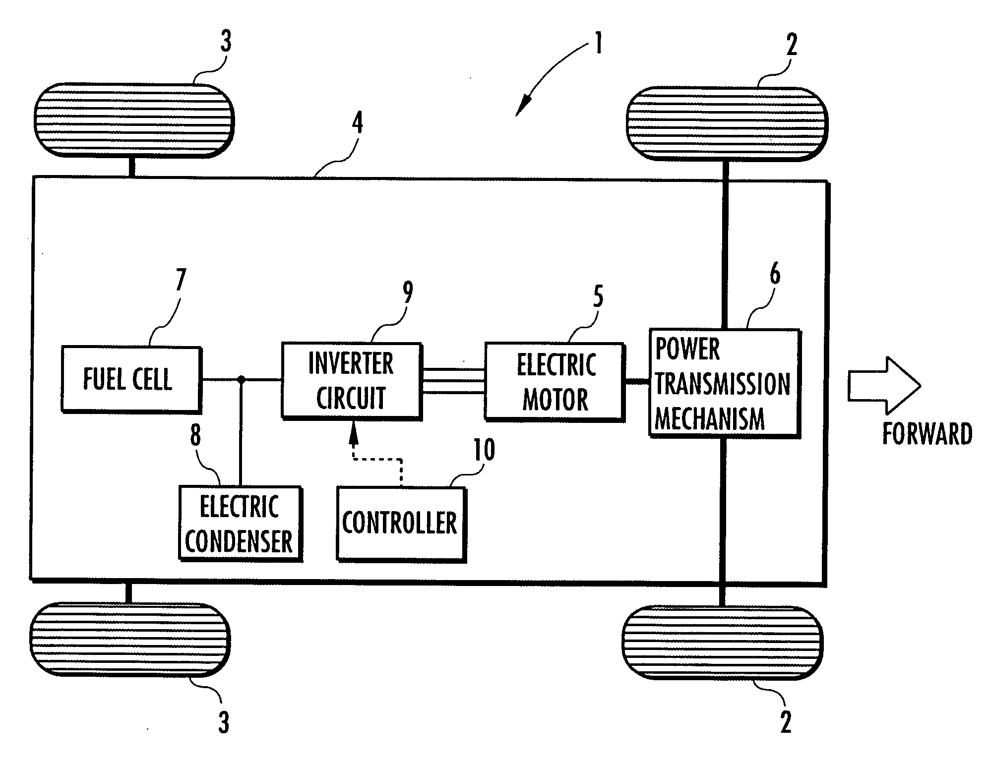
[0051]A vehicle in this embodiment is an electrically powered vehicle (electric automobile) that uses a fuel cell as a main energy source, for example. FIG. 1 is a schematic diagram showing a configuration of the electrically powered vehicle.

[0052]As shown in this drawing, an electrically powered vehicle 1 has a pair of left and right front wheels 2, 2, which are driving wheels, and a lateral pair of rear wheels 3, 3, which are driven wheels. An electric motor 5 serving as a propulsive force source for the vehicle 1 is mounted on a body 4 of the vehicle 1. A driving shaft 5a of the electric motor 5 is coupled to the driving wheels (front wheels) 2, 2 via a power transmission mechanism 6, which is composed of a transmission, a differential gear device and the like. Thus, a torque produced by the electric motor 5 is transferred to the driving wheels 2, 2 via the power transmission mechanism 6. The electric mo...


PUM


Abstract

An electric motor is coupled to driving wheels 2, 2. When a slippage of the driving wheels 2, 2 is detected, the electric motor 5 produces a regenerative torque to suppress the slippage of the driving wheels 2, 2. The regenerative torque is controlled in a variable manner according to an index parameter that indicates a road surface condition. Thus, when the slippage of the driving wheels occurs, the slippage of the driving wheels is suppressed according to the road surface condition by a regenerative operation of the electric motor coupled to the driving wheels.

Description

TECHNICAL FIELD[0001]The present invention relates to a traction control device for a vehicle that has an electric motor for selectively applying a driving torque or a regenerative torque to a driving wheel.BACKGROUND ART[0002]There has been known a conventional traction control device that controls a slippage of a driving wheel of a vehicle by applying a regenerative torque (braking torque) to the driving wheel from an electric motor. In general, the device of this type makes the electric motor produce a constant regenerative torque when the driving wheel slips.[0003]However, if the regenerative torque produced by the electric motor is constant, the regenerative torque easily becomes excessive or insufficient depending on the road surface condition. For example, in the case where the regenerative torque is relatively high, if the coefficient of friction of the road surface is relatively high, the slippage of the driving wheel tends to be abruptly eliminated, and thus, the accelerat...

Claims


Application Information

Patent Timeline
Patent Type & Authority Applications(United States)
IPC IPC(8): B60L7/10
CPCB60K28/16B60L3/06B60L3/102B60L7/26B60T2270/603B60W30/18127B60T8/175
Inventor YANAGIDA, HISANORISUGITA, YOSHINARIUENODAI, ASAOSHIRASAKA, TAKUYA
Owner HONDA MOTOR CO LTD
Learn More