Image projection apparatus
a technology of image projection and projection optics, which is applied in the field of image projection apparatus, can solve the problems of increasing the cost of the projection optic unit, the difficulty of widening the lens angle, and the large size of the entire apparatus, and achieves the effect of large aperture and easy small-sizing
- Summary
- Abstract
- Description
- Claims
- Application Information
AI Technical Summary
Benefits of technology
Problems solved by technology
Method used
Image
Examples
embodiment 1
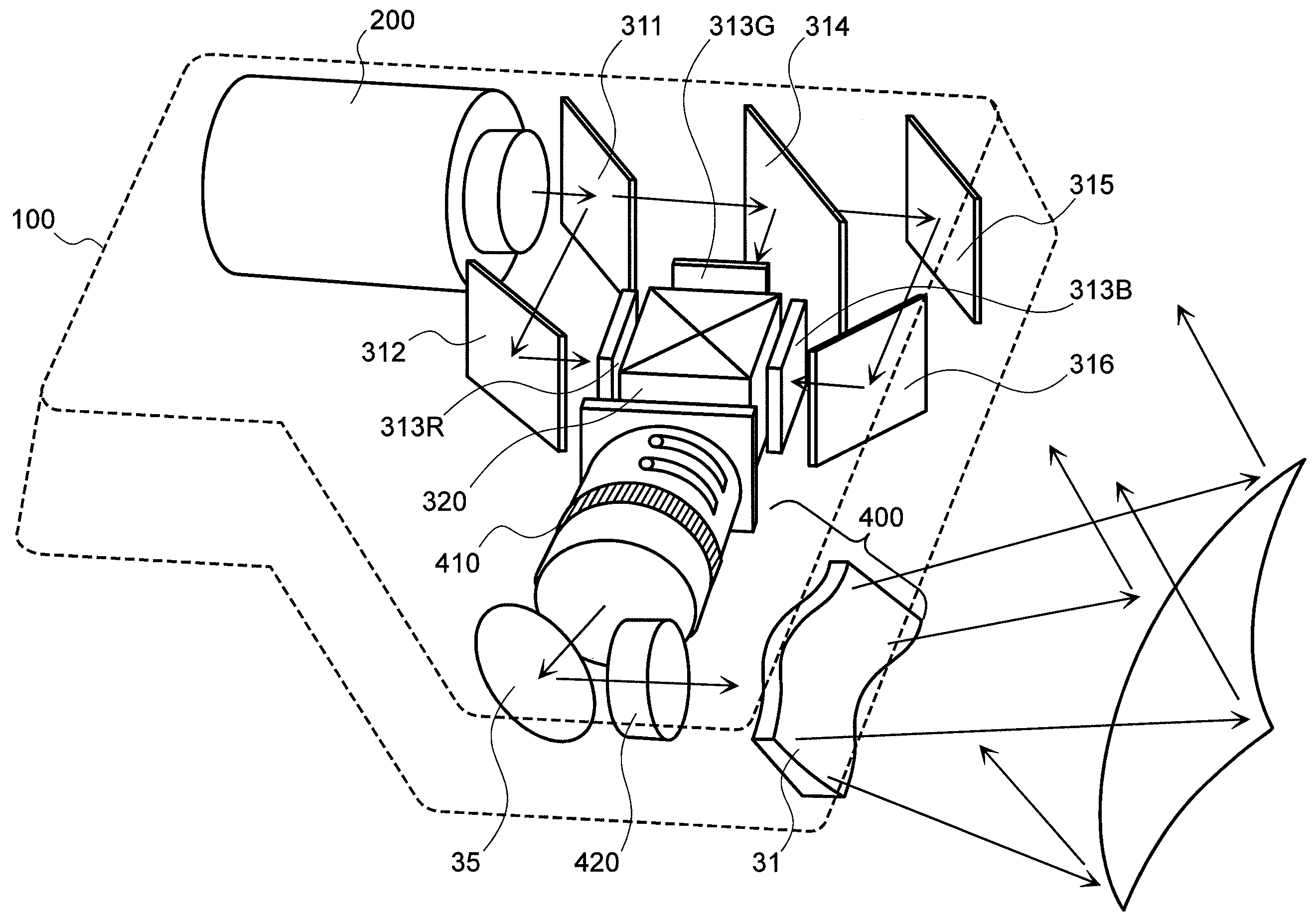
[0055]Firstly, explanation will be made on the details of the projection optic unit, according to the present embodiment explained in the above, by referring to FIGS. 8 and 9 attached herewith and further tables 1 to 4 below, while showing the detailed numerical values of the optical elements, including the lens optic system and the reflection optic system therein. However, FIGS. 8 and 9 attached herewith are diagrams for showing light beams in the optic system according to the present invention, upon basis of an example of first numerical values. Thus, within XYZ rectangular coordinates system shown in FIG. 2 mentioned above, FIG. 8 shows the Y-Z cross-section, i.e., extending the optic system into the Z-axis direction. Also, FIG. 9 shows the structures on X-Z cross-section, and in this FIG. 9 shows is disposed the bending mirror 35 on the way between the front lens group 2 and the rear lens group 3 building up the lens optic system, as is shown in the details thereof in FIGS. 5 an...
embodiment 2
[0071]Next, explanation will be made on a second embodiment by referring to tables 5 to 8. Herein, the front lens group 2 of the lens optic system is built up with the plural number of lenses, all of which have a refracting interface of rotationally symmetric configuration, and four (4) of the refracting interfaces of those lenses have aspheric surfaces, each being rotationally symmetric, and others have the spherical surfaces. The aspheric surface being rotationally symmetric, which is used therein, can be expressed by the equation mentioned above, with using a local cylindrical coordinates system for each surface. Also, the free curved surfaces building up the rear lens group 3 of the lens optic system mentioned above can be expressed by the equation mentioned above, including polynomials of X and Y, with applying the local coordinates system (x, y, z) assuming the apex on each surface to be the origin.
[0072]The following table 5 shows lends data of the present embodiment includ...
embodiment 3
[0081]Next, explanation will be made on a third embodiment, according to the present invention. Herein, also the front lens group 2 of the lens optic system is built up with the plural number of lenses, all of which have a refracting interface of rotationally symmetric configuration, and four (4) of the refracting interfaces of those lenses have aspheric surfaces, each being rotationally symmetric, and others have the spherical surfaces. The aspheric surface being rotationally symmetric, which is used therein, can be expressed by the equation mentioned above, with using a local cylindrical coordinates system for each surface. Also, the free curved surfaces building up the rear lens group 3 of the lens optic system mentioned above can be expressed by the equation mentioned above, including polynomials of X and Y, with applying the local coordinates system (x, y, z) assuming the apex on each surface to be the origin.
[0082]The following table 9 shows lends data of the third embodimen...
PUM
 Abstract
Description
Claims
Application Information
 - R&D
- Intellectual Property
- Life Sciences
- Materials
- Tech Scout
- Unparalleled Data Quality
- Higher Quality Content
- 60% Fewer Hallucinations
Browse by: Latest US Patents, China's latest patents, Technical Efficacy Thesaurus, Application Domain, Technology Topic, Popular Technical Reports.
© 2025 PatSnap. All rights reserved.Legal|Privacy policy|Modern Slavery Act Transparency Statement|Sitemap|About US| Contact US: help@patsnap.com


