

Heatless slurry system
- Summary
- Abstract
- Description
- Claims
- Application Information
AI Technical Summary
Benefits of technology
Problems solved by technology
Method used
Image


Examples
Embodiment Construction
[0017]The present invention is illustrated in further details by the following non-limiting examples.
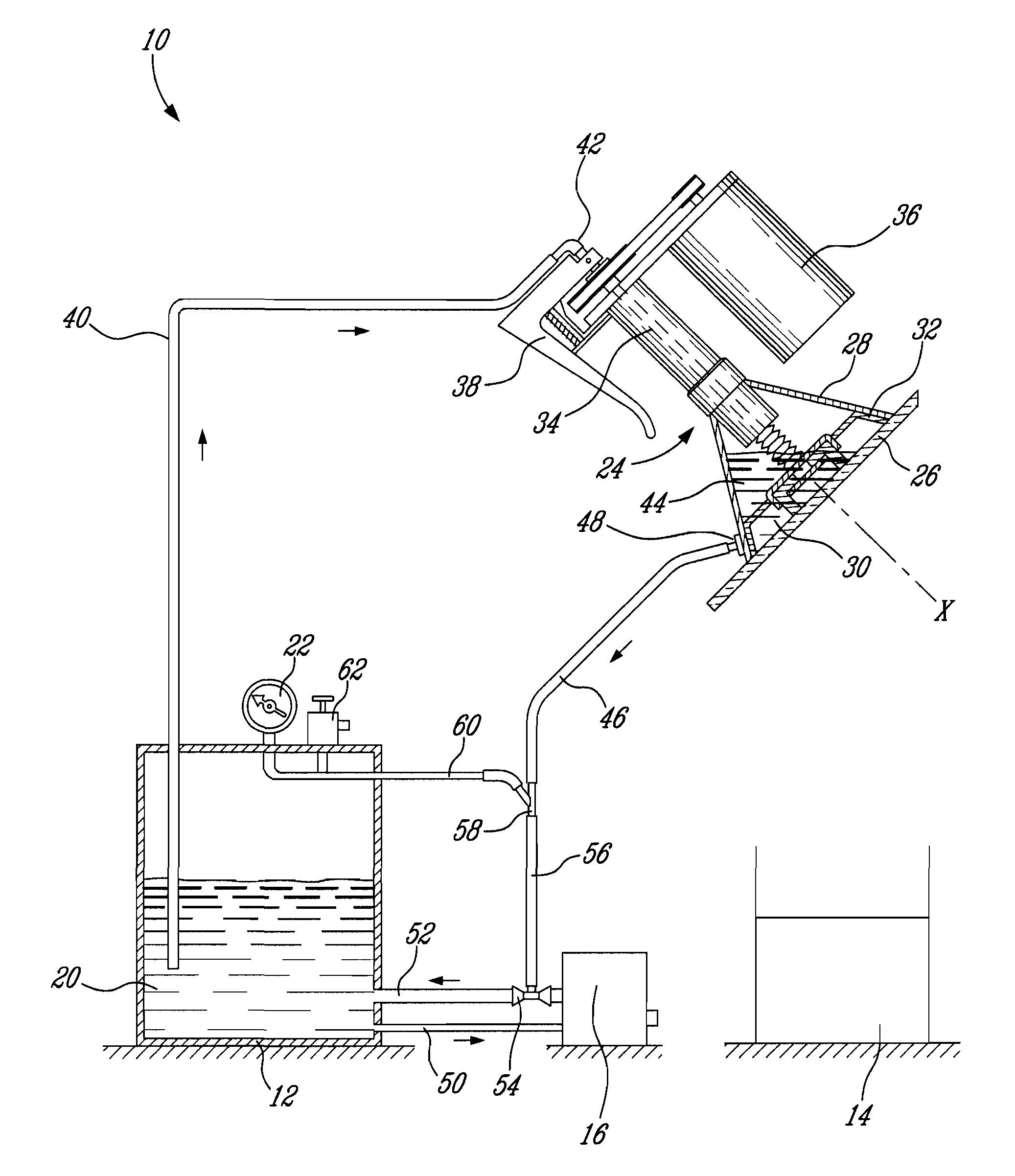
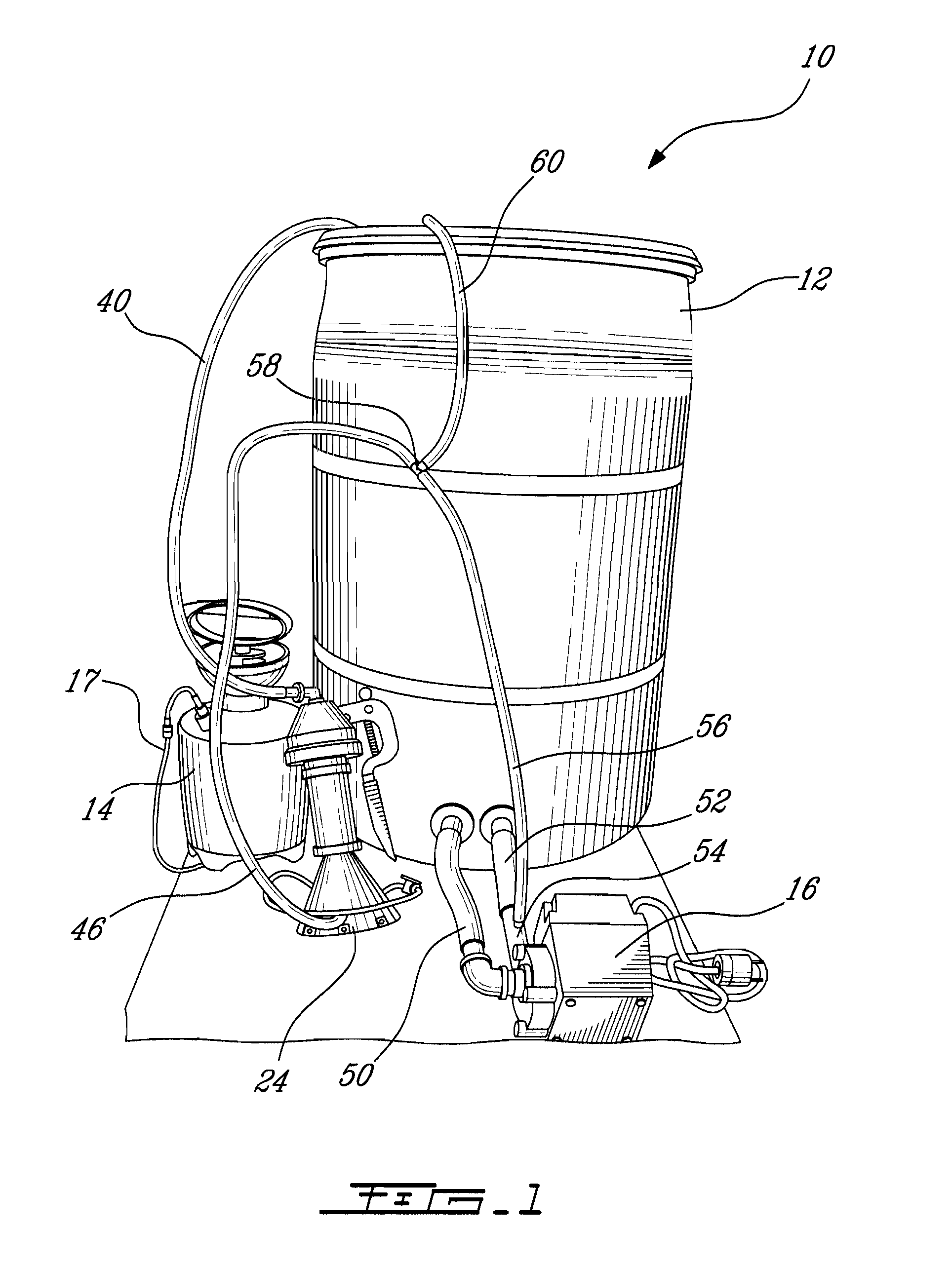
[0018]Referring now to FIG. 1, a heatless slurry system, generally referred to using the reference numeral 10, will now be described. The heatless slurry system 10 includes a slurry container 12 containing an abrasive slurry solution, a polishing tool 24 and a pump 16 illustratively positioned externally with respect to the container 12. As it will be apparent to those skilled in the art, the polishing tool 24 may be replaced by a fining tool or other similar tools for restoring a surface. A separate water tank 14 may be used as it will be explained further herein below. The pump 16 creates a vacuum effect that eases the displacement of the polishing tool 24 on a surface (e.g. glass 26 or the like, shown in FIG. 4) to be restored while also enabling the abrasive solution to be extracted from the container 12 into the tool 24 for restoring the surface. In particular, scratches, stains...
PUM
| Property | Measurement | Unit |
|---|---|---|
| Pressure | aaaaa | aaaaa |
| Vacuum | aaaaa | aaaaa |
| Perimeter | aaaaa | aaaaa |
Abstract
Description
Claims
Application Information