Joint mechanism

Active Publication Date: 2010-06-24
NABLESCO CORP
5 Cites 11 Cited by

AI-Extracted Technical Summary

Problems solved by technology

However, the system is provided with drawbacks that an interfering region of a robot is large, also a weight thereof is heavy, an inertia load is large or the like.
However, according to the direct spring balance system of hanging to expand the tension spring obliquely between the front end of the member provided on the upper side of the vertical arm and moved in parallel therewith while marinating to be vertical and the horizontal arm of the background art, an expanded portion of the member is large, also the weight is large, and therefore, when a range of operating the robot is going to be widened, a total of the apparatus is enlarged, the spring is exposed to outside, which is dangerous.
Further, sin...

Method used

[0030]According to the invention, the lubricant of the speed reducer 2a at inside of the speed reducer attaching bracket 2 is introduced into the cylinder 7 by connecting the speed reducer attaching bracket 2 and the cylinder 7 of the counterbalance system 10. Therefore, in comparison with a case in which the lubricant is used only at inside of the speed reducer 2 as in the background art, a total amount of the lub...

Benefits of technology

[0016]According to the invention, the speed reducer and the cylinder of the counterbalance system are connected and the lubricant of the speed reducer is introduced into the cylinder. Therefore, in comparison with a case of using the lubricant only at inside of the speed reducer as in the background art, a total amount of the lubricant is increased, and therefore, a rise in a temperature of the lubricant by using the speed reducer can be restrained, the speed reducer can be used in a stable state and early destruction of the speed reducer can be prevented.
[0017]Further, according to the invention, the total amount of the lubricant is increased, and therefore, an increase in a contamination degree of the lubricant by a wear powder at inside of the speed reducer can be restrained and the speed...

Abstract

There is provided a joint mechanism capable of restraining a rise in a temperature of a lubricant of a speed reducer, bringing the speed reducer into a stable operating state and preventing early destruction of the speed reducer.
There is provided a joint mechanism constituted by a base 1, a turning base 4 provided above the base and rotated, and an arm 6 a lower end portion is pivotably supported by the turning base, in which a speed reducer 2 for rotating the turning base is provided at inside of the base, a counterbalance system 10 constituted by a cylinder 7 pivotably supported above the turning base and filled with a lubricant, a piston 8 provided in a hermetically sealed state slidably in a longitudinal direction at inside of the cylinder, and a piston rod 9 one end portion of which is connected to the piston and other end portion of which is connected to the arm 6 is provided, the speed reducer and the cylinder of the counterbalance system are connected and a lubricant of the speed reducer is introduced into the cylinder.

Application Domain

Programme-controlled manipulatorMechanical apparatus +7

Technology Topic

Sacroiliac jointEngineering +4

Image

  • Joint mechanism
  • Joint mechanism
  • Joint mechanism

Examples

  • Experimental program(1)

Example

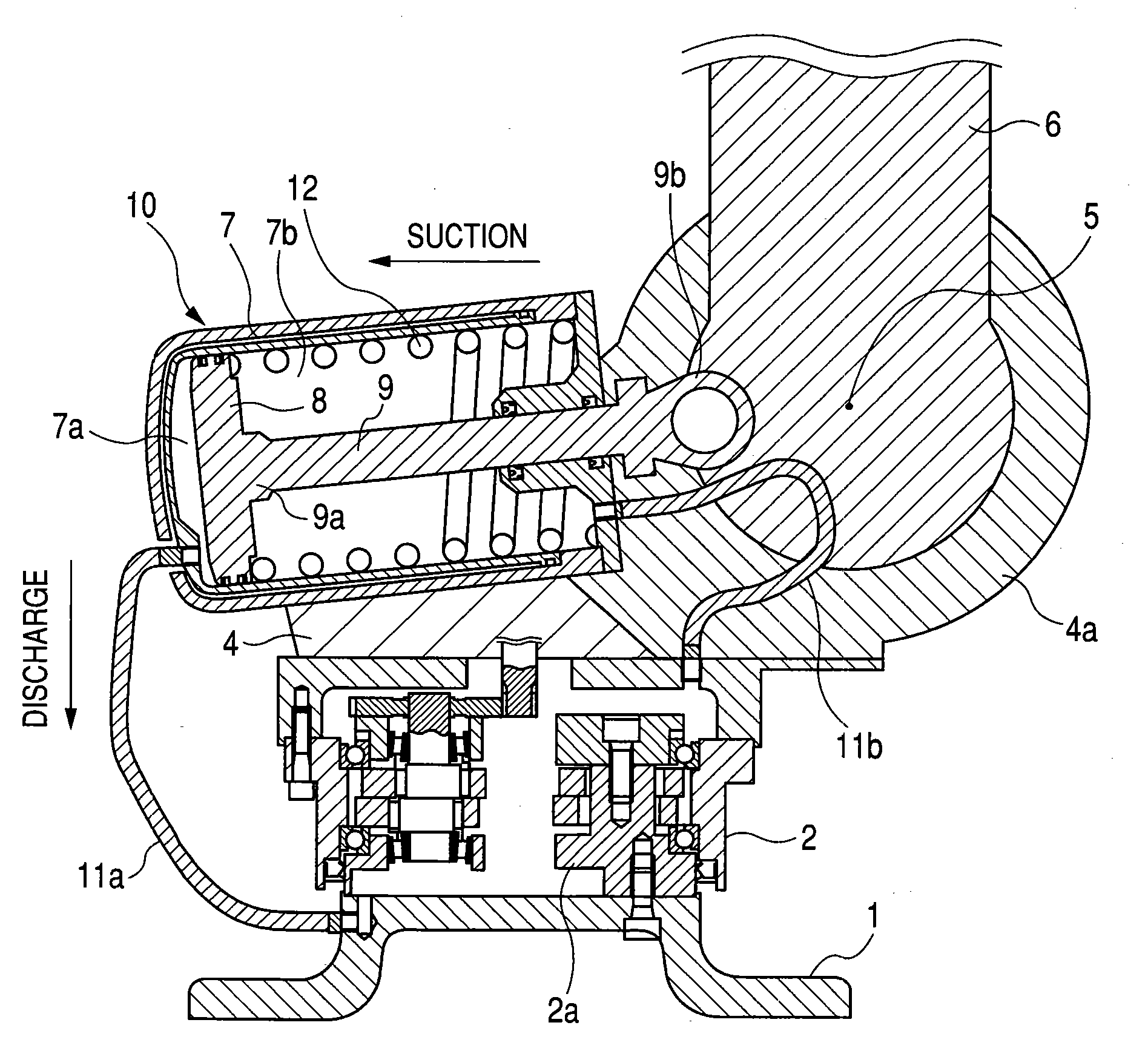
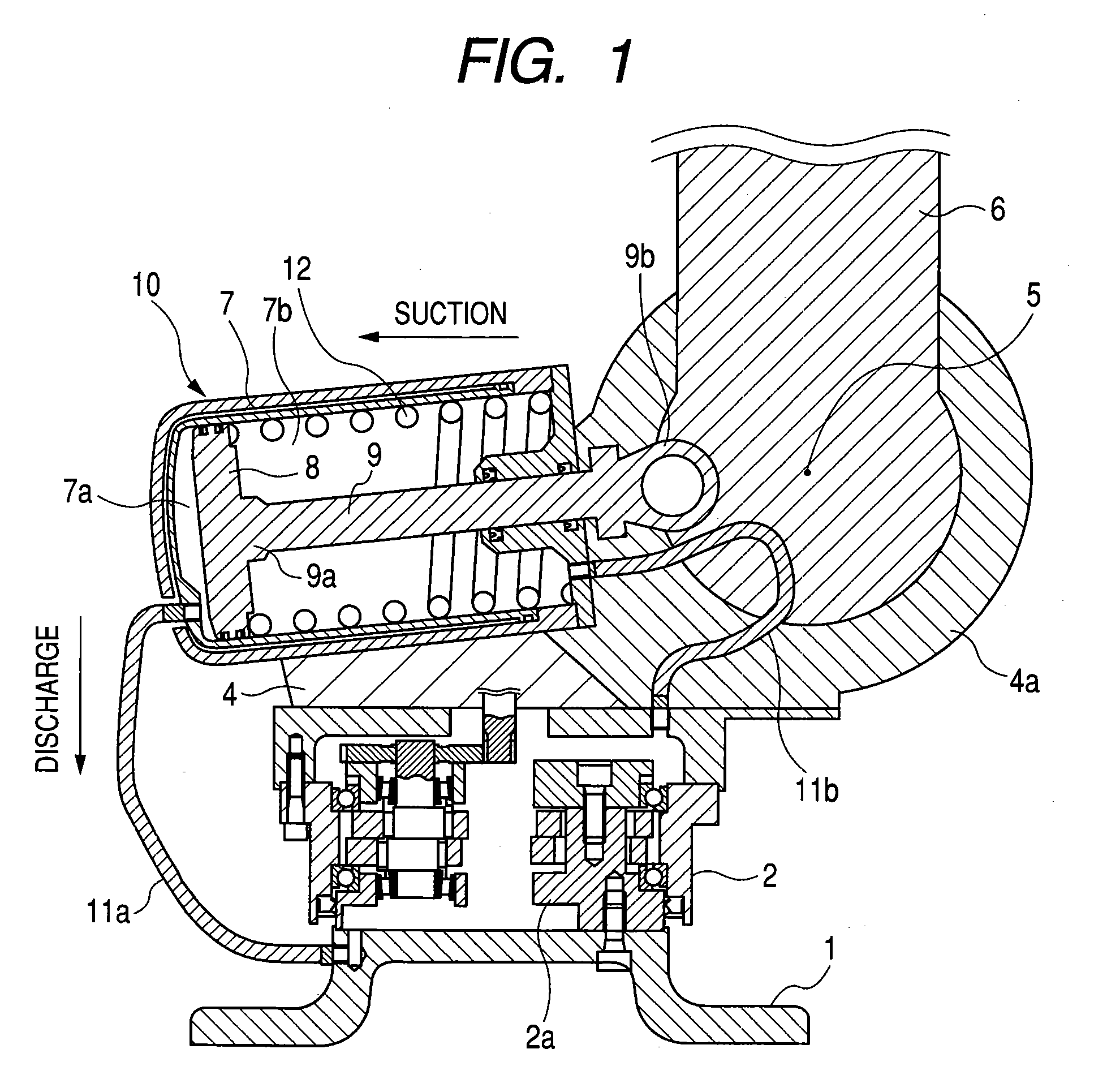
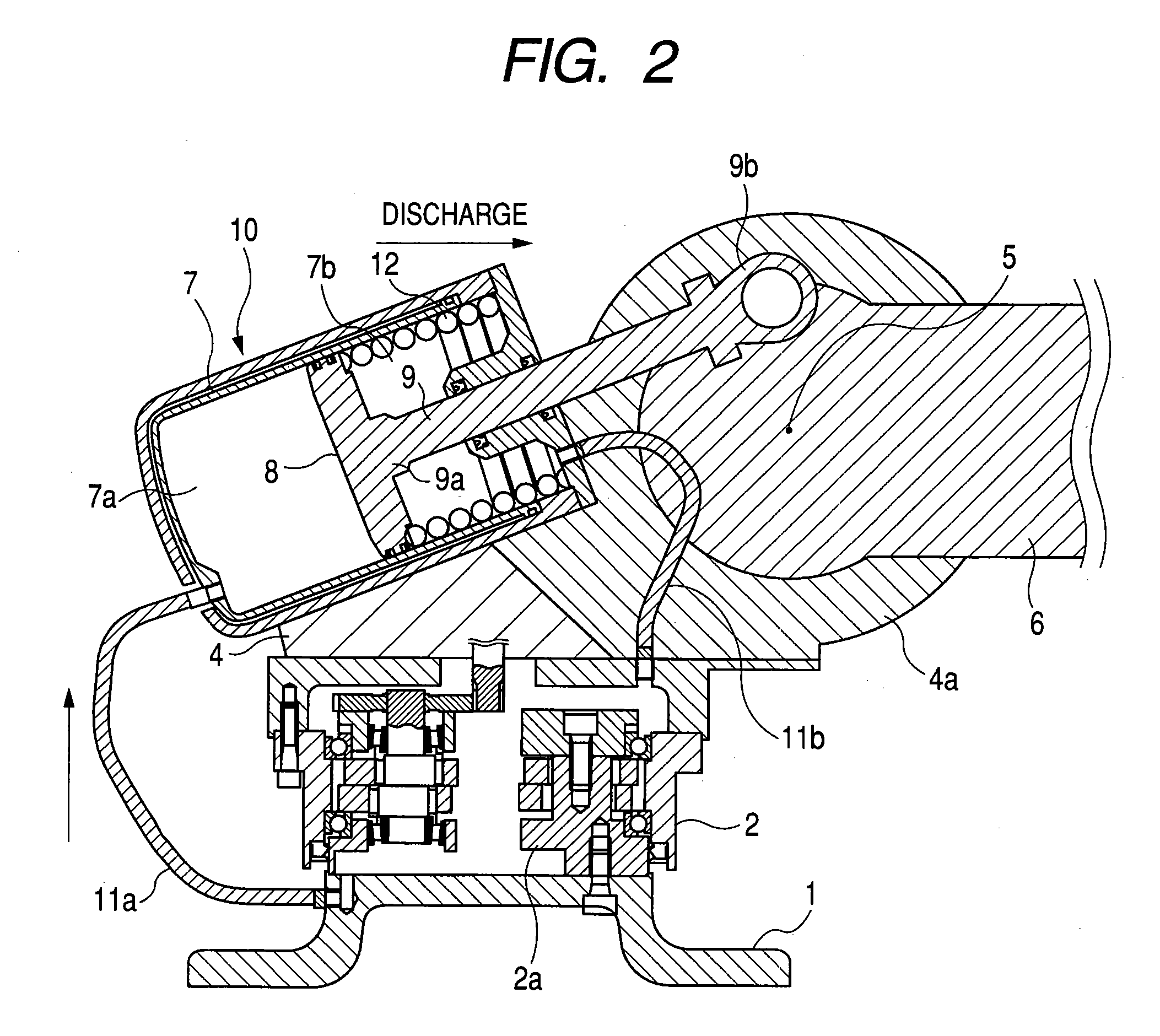
[0022]The invention will be explained in details in reference to the attached drawings illustrating an embodiment of the invention as follows. FIG. 1 is a sectional view of an essential portion of an embodiment of the invention embodied to a joint mechanism of an industrial robot, showing a state of sucking a lubricant to a right chamber at inside of a cylinder by moving a piston in a counter arm direction, and FIG. 2 shows a state of discharging the lubricant of the right chamber at inside of the cylinder by moving the piston in an arm direction in the embodiment of FIG. 1.
[0023]In FIG. 1 and FIG. 2, a speed reducer attaching bracket 2 is attached to a base 1 of an industrial robot, and a speed reducer 2a is provided at inside of the speed reducer attaching bracket 2. A style of the speed reducer 2a is not particularly limited but a publicly-known structure can be used, for example, a planetary gear apparatus comprising a crankshaft, a pinion formed with outer teeth at an outer periphery thereof, fitted to a crank portion of the crankshaft and eccentrically moved, and a case formed with inner teeth brought in mesh with the outer teeth of the pinion at an inner peripheral face thereof, or a wave gear speed reducer comprising a wave generator, a flex-spline and a circular spline or the like can be used.
[0024]A turning base 4 is provided above the base 1, the turning base 4 is rotated in a horizontal face by an output of the speed reducer 2a. A shaft portion 4a is provided above the turning base 4, a lower end portion of an arm 6 is supported by the shaft portion 4a pivotably around a horizontal axis line 5, and the arm 6 is pivoted in a vertical face by a power from a pivoting drive source (not illustrated). The joint mechanism of the invention is constituted as described above. Further, other end portion of the arm 6 is pertinently connected with other arm (not illustrated).
[0025]A cylinder 7 is supported by a pin pivotably between a pair of brackets (not illustrated) provided above the turning base 4. Inside of the cylinder 7 is provided with a piston 8 in a hermetically sealed state slidably in a longitudinal direction. One end portion 9a of a piston rod 9 is integrally connected to the piston 8 and other end portion 9b thereof is axially attached to the arm 6.
[0026]A counterbalance system 10 of the invention is constituted by the cylinder 7, the piston 8 and the piston rod 9. A left chamber 7a disposed on a left side of the piston 8 at inside of the cylinder 7 of the counterbalance system 10 and a right chamber 7b disposed on a right side thereof are respectively connected to the base 1 and the turning base 4 through hydraulic pipes 11a and 11b, a lubricant of the speed reducer 2a at inside of the speed reducer attaching bracket 2 is introduced into the cylinder 7 and the lubricant is filled at inside of the cylinder 7.
[0027]In the counterbalance system 10 of the embodiment, a compression spring 12 for urging the piston 8 to a counter side of the arm 6 is provided between an end face of the cylinder 8 on a side of the arm 6 and the piston 8, and the counterbalance system 10 always urges the arm 6 in the counterclockwise direction.
[0028]As shown by FIG. 1, when the arm 6 is pivoted in the counterclockwise direction, the piston 8 is moved in a left direction by the piston rod 9 connected to the arm 6, and the lubricant filled in the left chamber 7a at inside of the cylinder 7 is supplied to the speed reducer 2a bypassing the pipe 11a, and the lubricant of the speed reducer 2a is filled into the right chamber 7a at inside of the cylinder7 by passing the pipe 11b.
[0029]Conversely, as shown by FIG. 2, when the arm 6 is pivoted in the clockwise direction, the piston 8 is moved in a right direction by the piston rod 9 connected to the arm 6, the lubricant filled in the right chamber 7b at inside of the cylinder 7 passes the pipe 11b to be supplied to the speed reducer 2a, the lubricant of the speed reducer 2a passes the pipe 11a to be filled in the left chamber 7b at inside of the cylinder 7.
[0030]According to the invention, the lubricant of the speed reducer 2a at inside of the speed reducer attaching bracket 2 is introduced into the cylinder 7 by connecting the speed reducer attaching bracket 2 and the cylinder 7 of the counterbalance system 10. Therefore, in comparison with a case in which the lubricant is used only at inside of the speed reducer 2 as in the background art, a total amount of the lubricant is increased, and therefore, a rise in a temperature of the lubricant by using the speed reducer 2a is restrained, the speed reducer 2a can be used in a stable state, early destruction of the speed reducer 2a can be prevented, an increase in the contamination degree of the lubricant by a wear powder at inside of the speed reducer 2a can be restrained and the speed reducer 2a can be operated in a clean state.
INDUSTRIAL APPLICABILITY
[0031]According to the invention, the counterbalance system 10 can be constituted by a size to a degree the same as that of a counterbalance mechanism used in the background art, and therefore, the range of operating the apparatus provided with a joint mechanism of an industrial robot or the like is not hampered. Further, the size of the counterbalance system 10 of the invention is constituted by a size to a degree the same as that of the counterbalance mechanism used in the background art, and is applicable to all of industrial robots.
[0032]Further, according to the invention, the piston rod 9 of the counterbalance system 10 is connected to the arm 6, and a movement of the arm 6 can be utilized as a pump without separately preparing a power for the pump.

PUM

no PUM

Description & Claims & Application Information

We can also present the details of the Description, Claims and Application information to help users get a comprehensive understanding of the technical details of the patent, such as background art, summary of invention, brief description of drawings, description of embodiments, and other original content. On the other hand, users can also determine the specific scope of protection of the technology through the list of claims; as well as understand the changes in the life cycle of the technology with the presentation of the patent timeline. Login to view more.

Similar technology patents

Vehicle and method for controlling vehicle

PendingUS20200231060A1temperature risereduce amount of heat
Owner:TOYOTA JIDOSHA KK

Air cleaner apparatus

InactiveUS20110067367A1improve efficiencytemperature rise
Owner:HONDA MOTOR CO LTD

Heatless slurry system

ActiveUS20090117834A1temperature rise
Owner:SAUVE VITRES

Compositions and methods for imaging and treatment

ActiveUS20160038610A1increase in temperature
Owner:NEW YORK UNIV IN ABU DHABI CORP

Display panel inspection apparatus and method

InactiveUS20080030725A1reliably detectincrease in temperature
Owner:FUJITSU LTD

Classification and recommendation of technical efficacy words

  • temperature rise
  • increase in temperature

Heatless slurry system

ActiveUS20090117834A1temperature rise
Owner:SAUVE VITRES

Vehicle and method for controlling vehicle

PendingUS20200231060A1temperature risereduce amount of heat
Owner:TOYOTA JIDOSHA KK

Air cleaner apparatus

InactiveUS20110067367A1improve efficiencytemperature rise
Owner:HONDA MOTOR CO LTD

Temperature controlled solute delivery system

InactiveUS7407671B2increase in gel temperatureincrease in temperature
Owner:BOSTON SCI SCIMED INC

Methods and systems for operating an engine

ActiveUS20110253113A1increase exhaust temperatureincrease in temperature
Owner:GE GLOBAL SOURCING LLC

Shockwave catheter system with energy control

ActiveUS20140074111A1increase in temperaturedecrease energy
Owner:SHOCKWAVE MEDICAL

Integrated vehicle fluids

ActiveUS20120227374A1reduce peak pressureincrease in temperature
Owner:UNITED LAUNCH ALLIANCE
Why Eureka
Try Eureka