

Air cleaner apparatus
- Summary
- Abstract
- Description
- Claims
- Application Information
AI Technical Summary
Benefits of technology
Problems solved by technology
Method used
Image

Examples
first embodiment
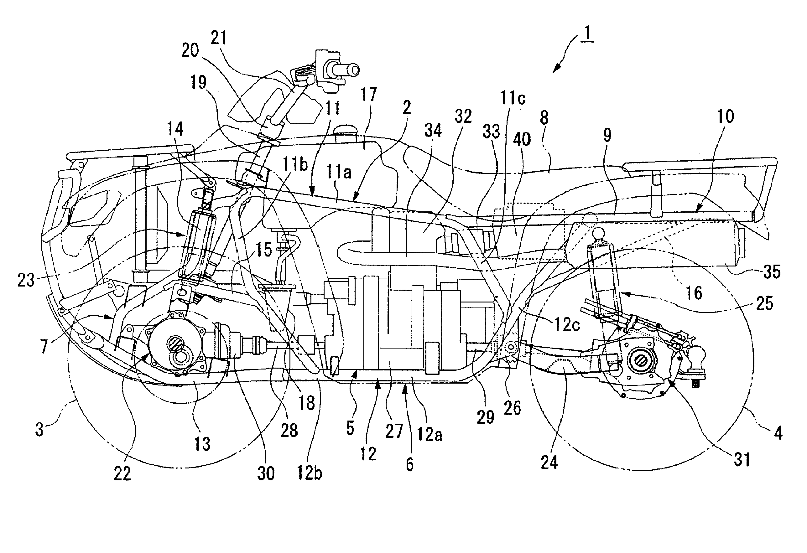
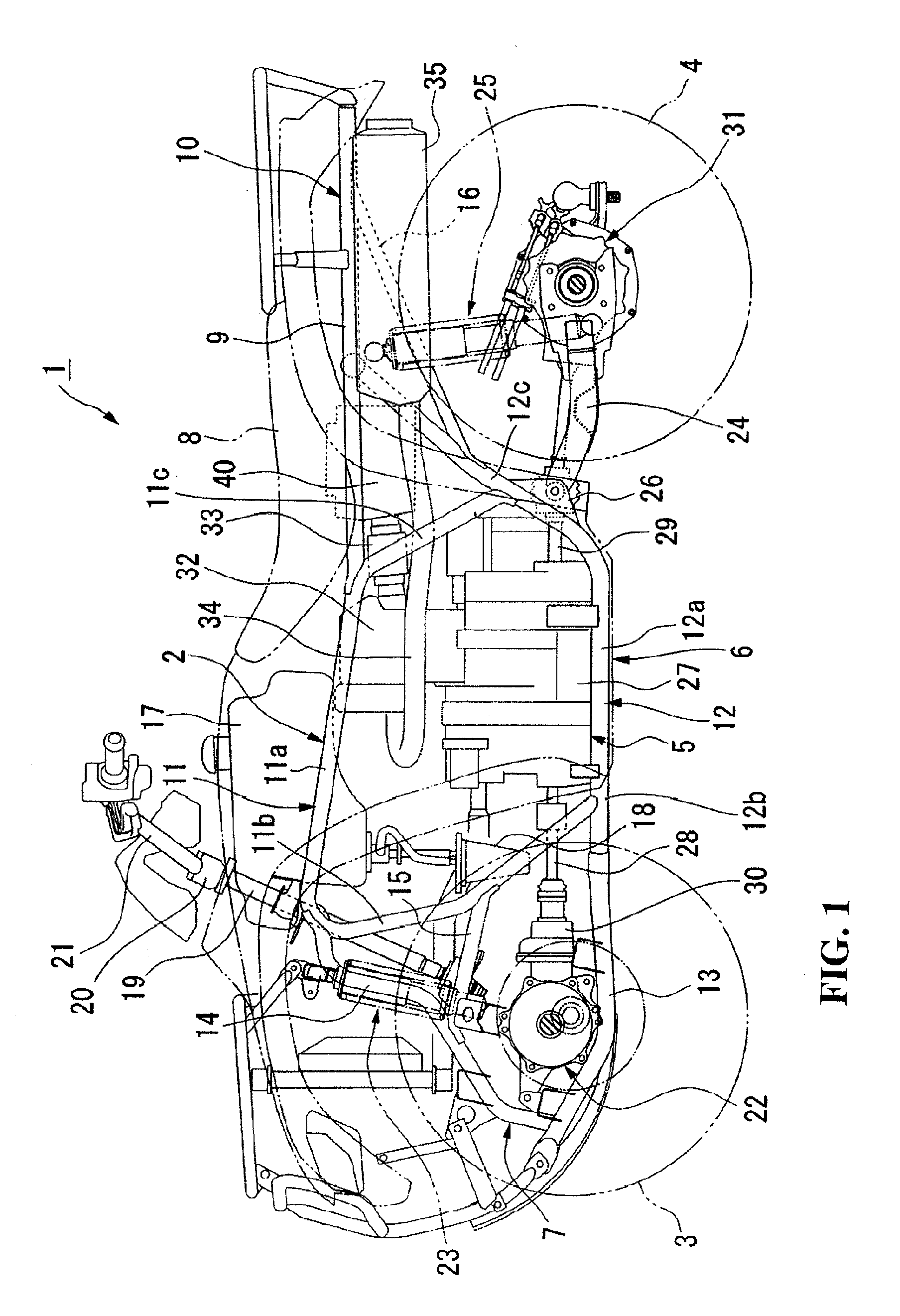
[0047]FIG. 1 shows a saddle-ride type four-wheeled vehicle 1 as an example of a vehicle mounted with an air cleaner apparatus according to the present invention. Now, the saddle-ride type four-wheeled vehicle 1 will be described first. It should be noted that in the drawings used in the following description, the arrow FR and the arrow UP indicate the front side of the vehicle and the upper side of the vehicle, respectively, which will be properly used in the following description. Also, the saddle-ride type four-wheeled vehicle 1 is an example of a vehicle on which the air cleaner apparatus according to the present invention can be mounted, and the air cleaner apparatus can be also mounted on another type of vehicle such as a motorcycle, for example.
[0048]The saddle-ride type four-wheeled vehicle 1 is a so-called ATV (All Terrain Vehicle), in which left and right front wheels 3 and rear wheels 4 that are low pressure balloon tires of a relatively large diameter are disposed at the ...
second embodiment
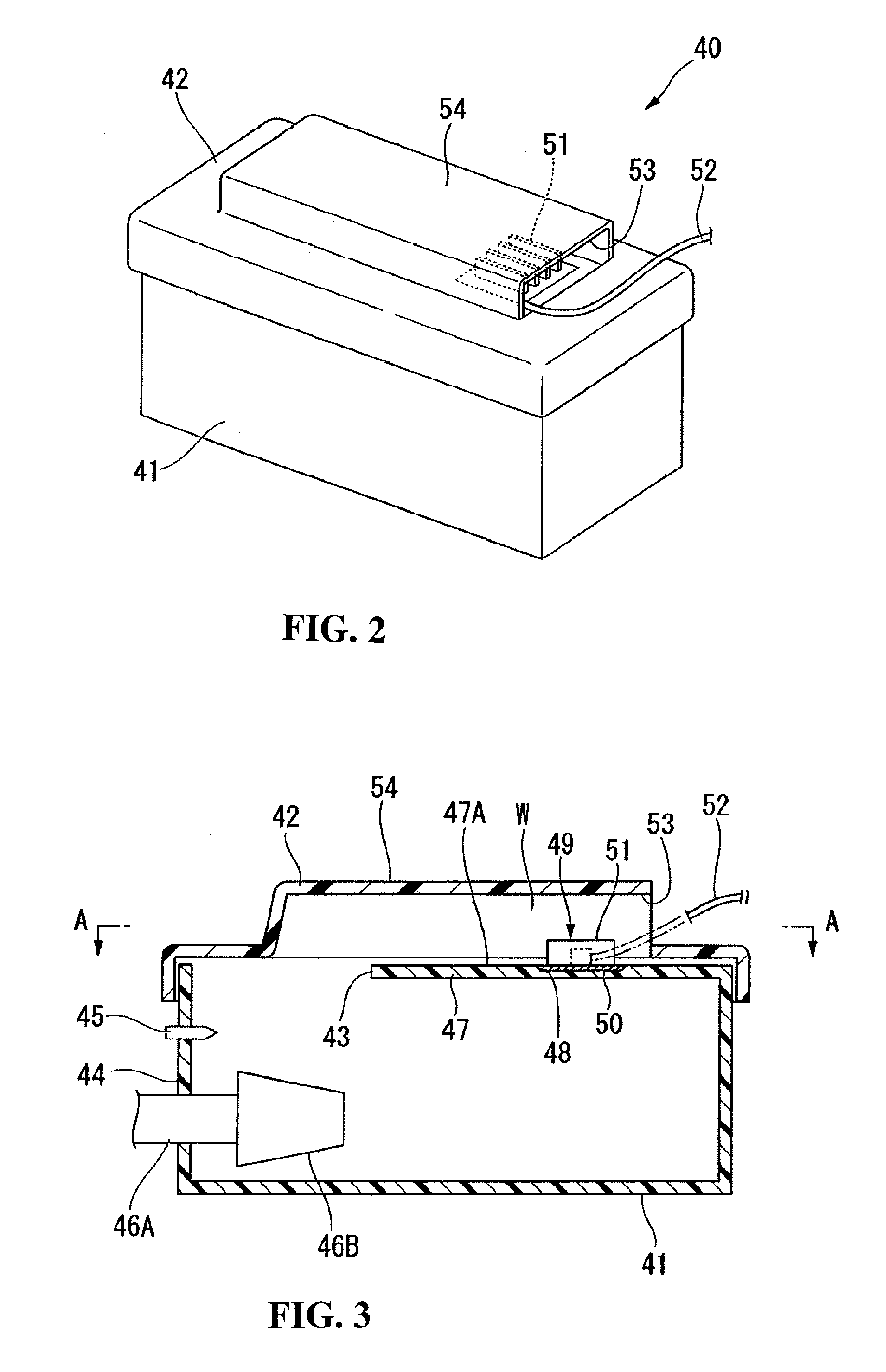
[0085]Therefore, in the second embodiment described above, since the regulator 49 as electrical equipment is placed inside the intake port 79, active forced-air cooling is provided to enable an improvement in the efficiency of cooling of the electrical equipment. In addition, since an intake air flow (cooling air flow) can be supplied to the regulator 49 in a stable manner both when the vehicle is running and when it is at a stop, a rise in the temperature of the regulator 49 can be effectively suppressed. Furthermore, when performing maintenance such as replacing or the like of the element 46B of the air cleaner apparatus 60, the first lid 62 is removed to make access to the interior of the air cleaner box 61. At this time, since the regulator 49 is attached not to the first lid 62 but to the air cleaner box 61 side, the regulator 49 does not become obtrusive when performing maintenance, in particular, when removing the first lid 62 to replace the element 46B. Therefore, the ease o...
third embodiment
[0091]Therefore, in the third embodiment as described above, an intake air flow W1 admitted from the intake port 53 is smoothly guided to the radiator fm 51 along the inclined surface of the guide portion 90, and an intake air flow W2 having passed through the radiator fin 51 is smoothly sent to the air cleaner box 41 side along the inclined surface of the guide portion 91. Thus, an intake air flow can be gathered to the radiator fm 51 to enable a further improvement in cooling efficiency. In addition, since the intake air flow is guided not to the substrate portion 50 but to the radiator fin 51 by the guide portions 90, 91, intake resistance can be reduced.
[0092]While a modification of the first embodiment is illustrated in the third embodiment, the guide portions 90, 91 mentioned above may be applied to the second embodiment and formed on the upper surface of the second lid 63. The same effect as that described above can be obtained in this case as well.
PUM
| Property | Measurement | Unit |
|---|---|---|
| Velocity | aaaaa | aaaaa |
| Injection velocity | aaaaa | aaaaa |
Abstract
Description
Claims
Application Information