

Vehicle and method for controlling vehicle
- Summary
- Abstract
- Description
- Claims
- Application Information
AI Technical Summary
Benefits of technology
Problems solved by technology
Method used
Image

Examples
first embodiment
Modification of First Embodiment
[0117]In a modification of the first embodiment, a process of switching cooling speed Qc of battery 14 in the constant current calculation process in accordance with whether or not air-conditioning of the vehicle cabin is performed will be described. An overall flow of external charging control in the modification of the first embodiment is common to the overall flow in the first embodiment (see FIG. 6).
[0118]FIG. 8 is a flowchart showing a constant current calculation process in the modification of the first embodiment. Referring to FIG. 8, the process in S81 to S83 is the same as the process in S21 to S23 in the first embodiment, respectively.
[0119]In S84, ECU 10 determines whether or not air-conditioning (cooling operation) of the vehicle cabin is performed. When the cooling operation is performed (YES in S84), ECU 10 calculates Qc1 as the cooling speed of battery 14 by air-conditioning and cooling system 15 (S851). In contrast, when the cooling op...
second embodiment
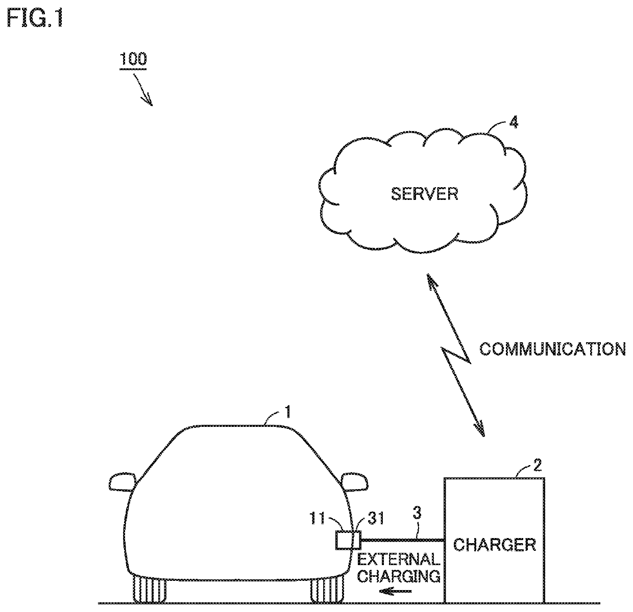
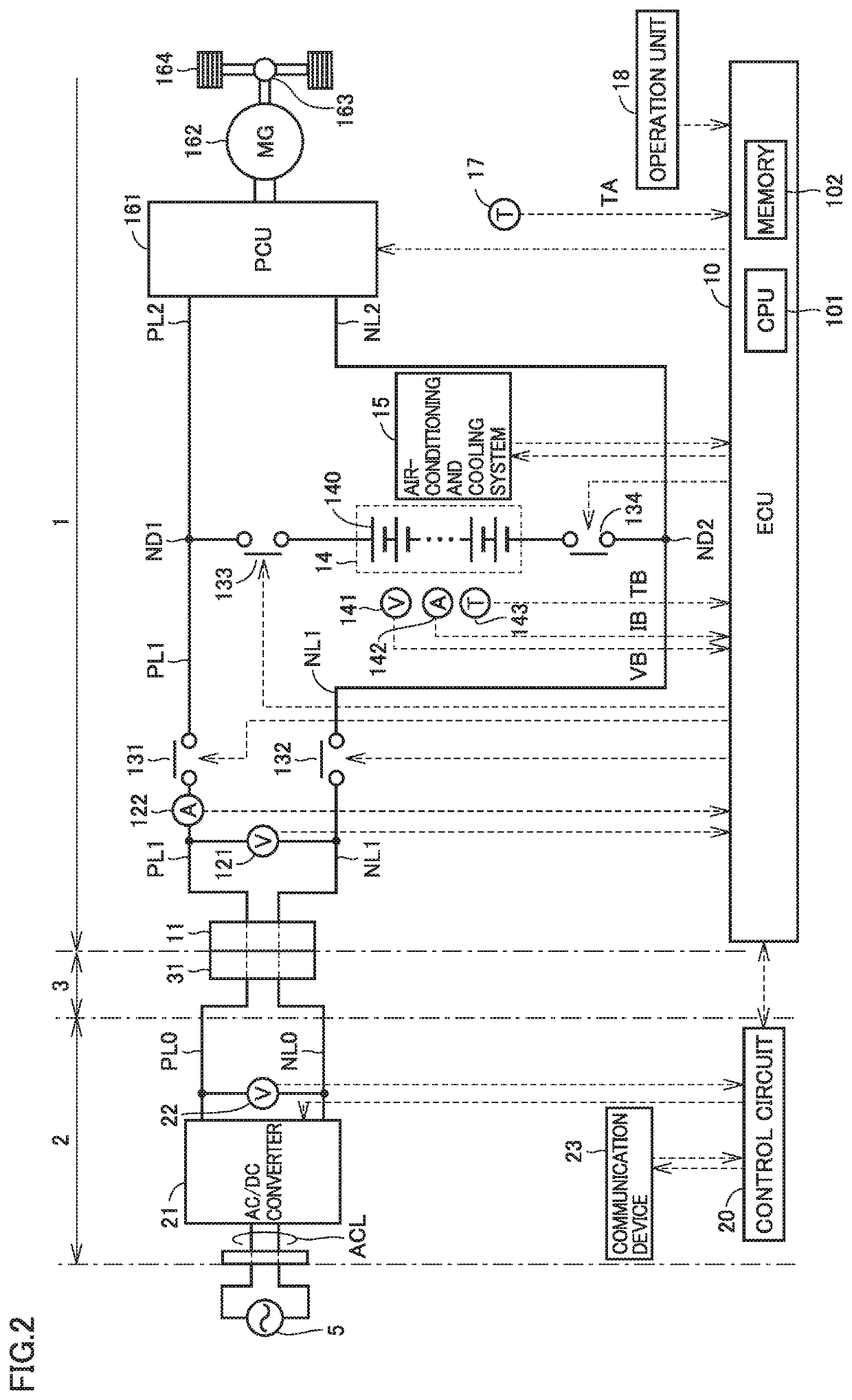
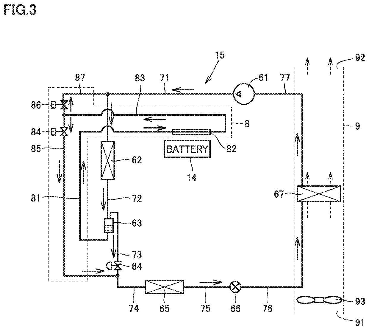
[0126]In a second embodiment, a configuration in which vehicle 1 has a plurality of (specifically, three) charging modes that can be selected by the user will be described. The three charging modes are a normal mode, a long-life mode for preventing deterioration of battery 14 and extending the life of battery 14, and a time reduction mode for further shortening the charging, time of battery 14. A configuration of the vehicle in the second embodiment is the same as the configuration of vehicle 1 in the first embodiment (see FIGS. 1 to 3).
[0127]FIG. 9 is a flowchart showing external charging control in the second embodiment. Referring to FIG. 9, similarly to the flowchart shown in FIG. 6 in the first embodiment, this flowchart is executed when the user operates operation unit 18 and performs an operation for requesting external charging of vehicle 1, with connector 31 of charging cable 3 inserted into inlet 11.
[0128]Referring to FIG. 9, in S91, ECU 10 obtains a user operation for sele...
PUM
 Abstract
Description
Claims
Application Information