Method for determining the liquid level in a boiler

Inactive Publication Date: 2010-05-06
KONINKLIJKE PHILIPS ELECTRONICS NV
View PDF42 Cites 19 Cited by
  • Summary
  • Abstract
  • Description
  • Claims
  • Application Information

AI Technical Summary

Benefits of technology

[0008]According to a specific embodiment it is preferred that the temporary deflection of the temperature is induced by turning on a heating device for heating the liquid. This embodiment refers to the above described case in which the steam generating system is powered on such that the temperature rises due to operating a heating device. In this embodiment the temporary deflection is a temperature overshot.
[0009]Advantageously, the liquid level is determined as low, if the evaluation temperature is greater than or equal to a first low level threshold. Having an additional reference value, for example the temperature at the start of the heating or the temperature at which the heating device is turned off, only the evaluation temperature is necessary to determine the liquid level inside the boiler.
[0010]In accordance with an embodiment of the invention, the heating device stays turned on until the temperature is greater than or equal to a first threshold temperature. In this embodiment, this is the relevant time for starting the monitoring for determining an extreme temperature. After passing the threshold temperature and turning off the heating device, the temperature still rises up to a peak or a maximum value before it lowers again such that the temperature course describes the overshot.
[0011]In a specific embodiment, the liquid level is determined as low, if the difference between the evaluation temperatu

Problems solved by technology

A water level sensor which would be arranged inside the boiler would very soon provide inaccurate results due to calcification of the inside of the boiler or the usage of de-mineralized water which can cause inaccurate sensing.
However, actuating the pump according to the value of the slope of the curve representing variation in temperature requires a very accurate and expensive temperature sensor since this slope method requires a very direct heat transfer through a thin wall such that slightest variations of the slope of the curve are detected.
Also the mounting of such an temperature se

Method used


Image

  • Method for determining the liquid level in a boiler
  • Method for determining the liquid level in a boiler
  • Method for determining the liquid level in a boiler

Examples


Example

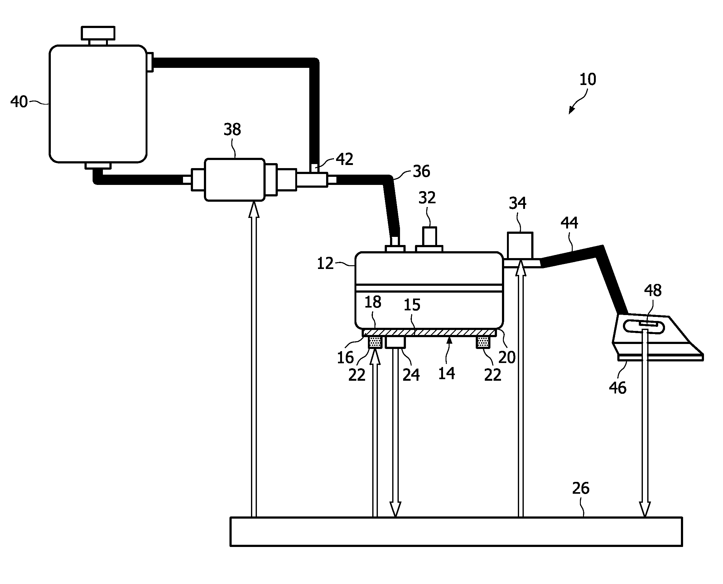
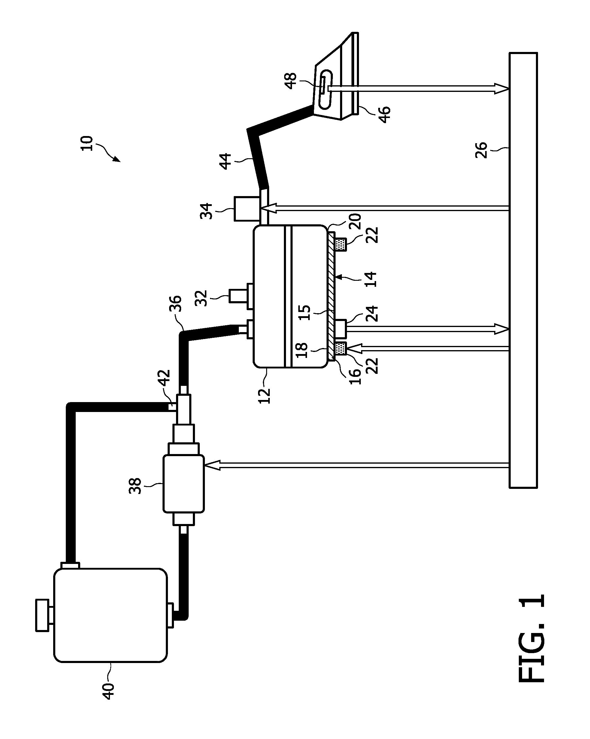
[0025]FIG. 1 shows a schematic set up of a steam generating device 10 according to the present invention. The steam generating device 10 comprises a water boiler 12 being manufactured by connecting at least two formed metal shells of stainless steal. The boiler 12 has a flat bottom portion 16 and is mounted in a plastic enclosure in a horizontal arrangement. Other orientations like a non horizontal arrangement are also possible. The flat bottom portion 16 of the boiler 12 is attached to a heating device 14 comprising a heating plate 15 and a heating element 22 which is attached to the heating plate 15 by forming an intermetallic layer or by casting to improve the heat transfer. The heating plate is made of aluminum—an aluminum alloy or other materials with excellent heat conductivity can also be used. The heating plate 15 comprises a flat upper portion 18 and is attached with its flat upper portion 18 to the flat bottom portion 16 of the body 12 by formation of an intermetallic laye...


PUM


Abstract

The present invention relates to a method of determining a liquid level in a boiler (12) of an apparatus (10) having a temperature sensor (24) for sensing a temperature (T) which is indicative of a temperature of the liquid inside the boiler (12), comprising the steps of: inducing a temporary deflection of the temperature (T) sensed by the temperature sensor (24); determining an evaluation temperature (Tev) sensed by the temperature sensor (24) after inducing the deflection; and determining the liquid level from at least the evaluation temperature (Tev). Advantageously, the invention provides that the evaluation temperature (Tev) is determined by monitoring the deflection and by defining an extreme value (Tmax, Tmin) of the deflection as the evaluation temperature (Tev). Further, the present invention relates to an steam generating apparatus adapted for executing such a method, a domestic appliance having such a steam generating apparatus.

Description

FIELD OF THE INVENTION[0001]The present invention generally relates to a method of determining a liquid level in a boiler of an apparatus having a temperature sensor for sensing a temperature which is indicative of a temperature of the liquid inside the boiler, comprising the steps of: inducing a temporary deflection of the temperature sensed by the temperature sensor; determining an evaluation temperature sensed by the temperature sensor after inducing the deflection; and determining the liquid level from at least the evaluation temperature.BACKGROUND OF THE INVENTION[0002]Steam generating apparatuses are used for heating water in order to generate steam which can be used for example for ironing cloth. In these apparatuses the steam is generated within a boiler in which the temperature of the water can be controlled within a certain temperature range by means of a heating device and a temperature sensor as follows: When the temperature signal of the temperature sensor indicates, th...

Claims


Application Information

Patent Timeline
IPC IPC(8): A47J31/44G01F23/00A47J27/00
CPCD06F75/12F22B1/285G01F23/246G01F23/22F22B37/78F22B1/28G01F23/24
Inventor XIAO, TAIKANGTHIRUMAZHISAI SANKARALINGAM, TAMILSELVANESTRADA, JOSE LUISTIEW, HOCK SOONBELLE, CHAITHRACHADHA, JASMEET SINGHTAY, BARRY ENG KEONG
Owner KONINKLIJKE PHILIPS ELECTRONICS NV
Why Eureka
Try Eureka