Frictionless descender for abseiling along a rope

a descender and frictionless technology, applied in the field of self-locking descenders, can solve the problems of operator fatigue, excessive wear of the need for frequent replacement, and achieve the effect of reducing the destructive heat and wear on the rope and descender

Inactive Publication Date: 2009-05-14
ARMS JOHNNY WAYNE
View PDF7 Cites 41 Cited by
  • Summary
  • Abstract
  • Description
  • Claims
  • Application Information

AI Technical Summary

Benefits of technology

[0007]The reason for this invention is to eliminate the destructive heat and wear on the rope and descender cau

Problems solved by technology

The friction causes excessive wear of the rope and descender which require frequent replacing.
Descenders that require the squeezing actio

Method used


Image

  • Frictionless descender for abseiling along a rope
  • Frictionless descender for abseiling along a rope
  • Frictionless descender for abseiling along a rope

Examples


Embodiment Construction

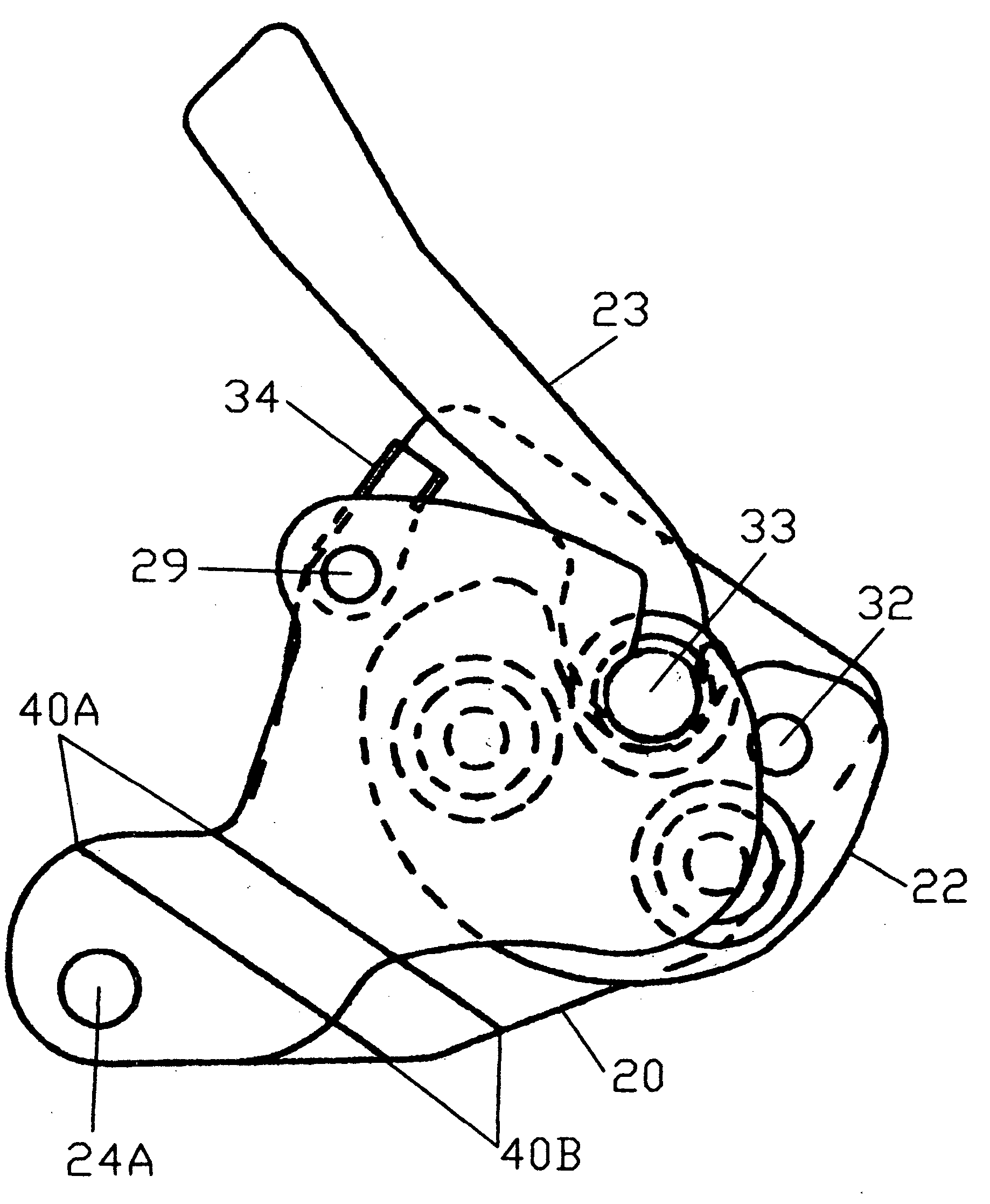
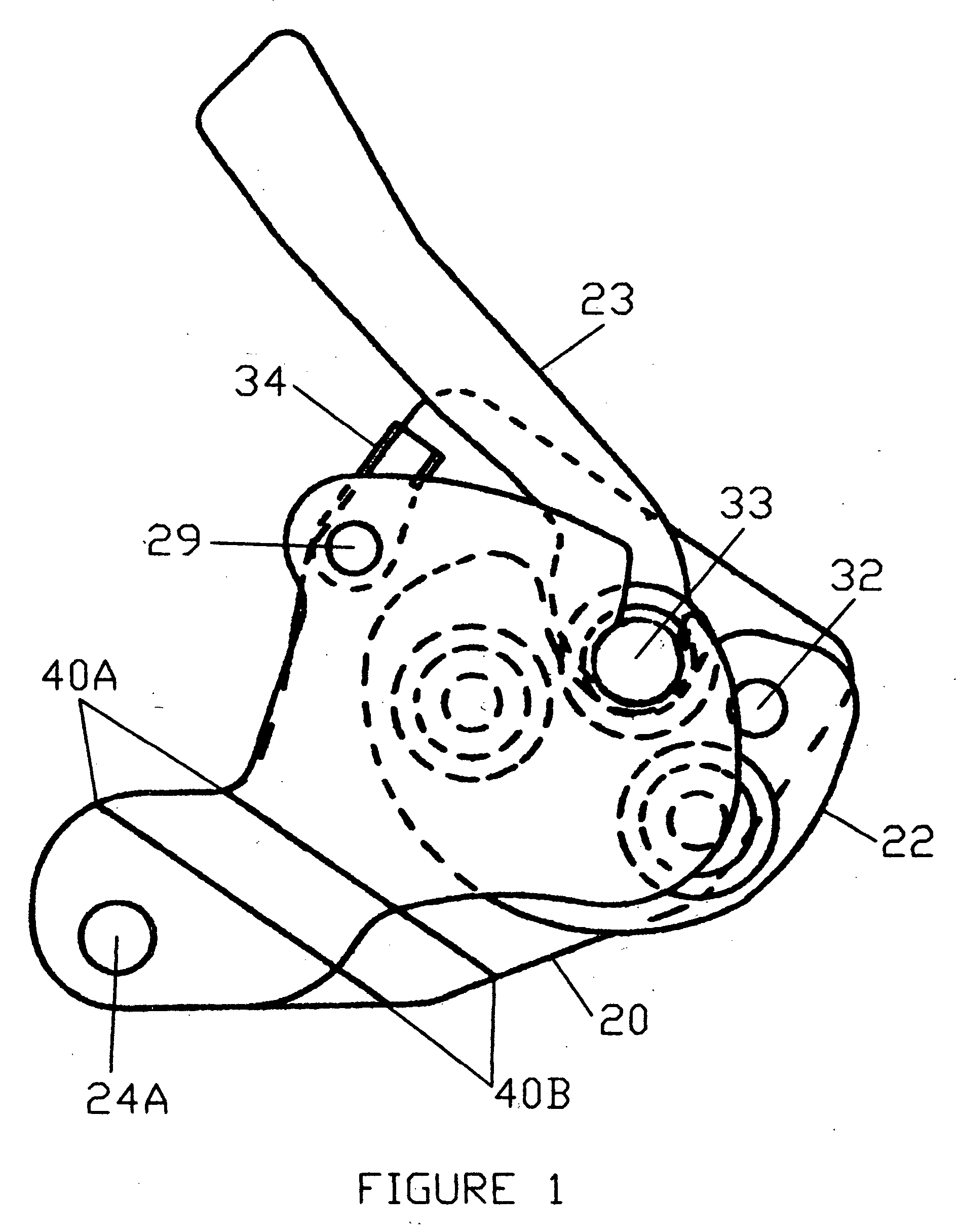
[0017]FIG. 6 shows the base plate 20 and the arrangements for stationary pulley stud 33, door stud 29, and pivoting plate stud 32. The bends 40B of base plate 20 and the connection point 24A are also indicated in FIG. 6.

[0018]FIG. 5 shows the angles and bends required in the base plate 20 and the door plate 21 to encase the other embodiments.

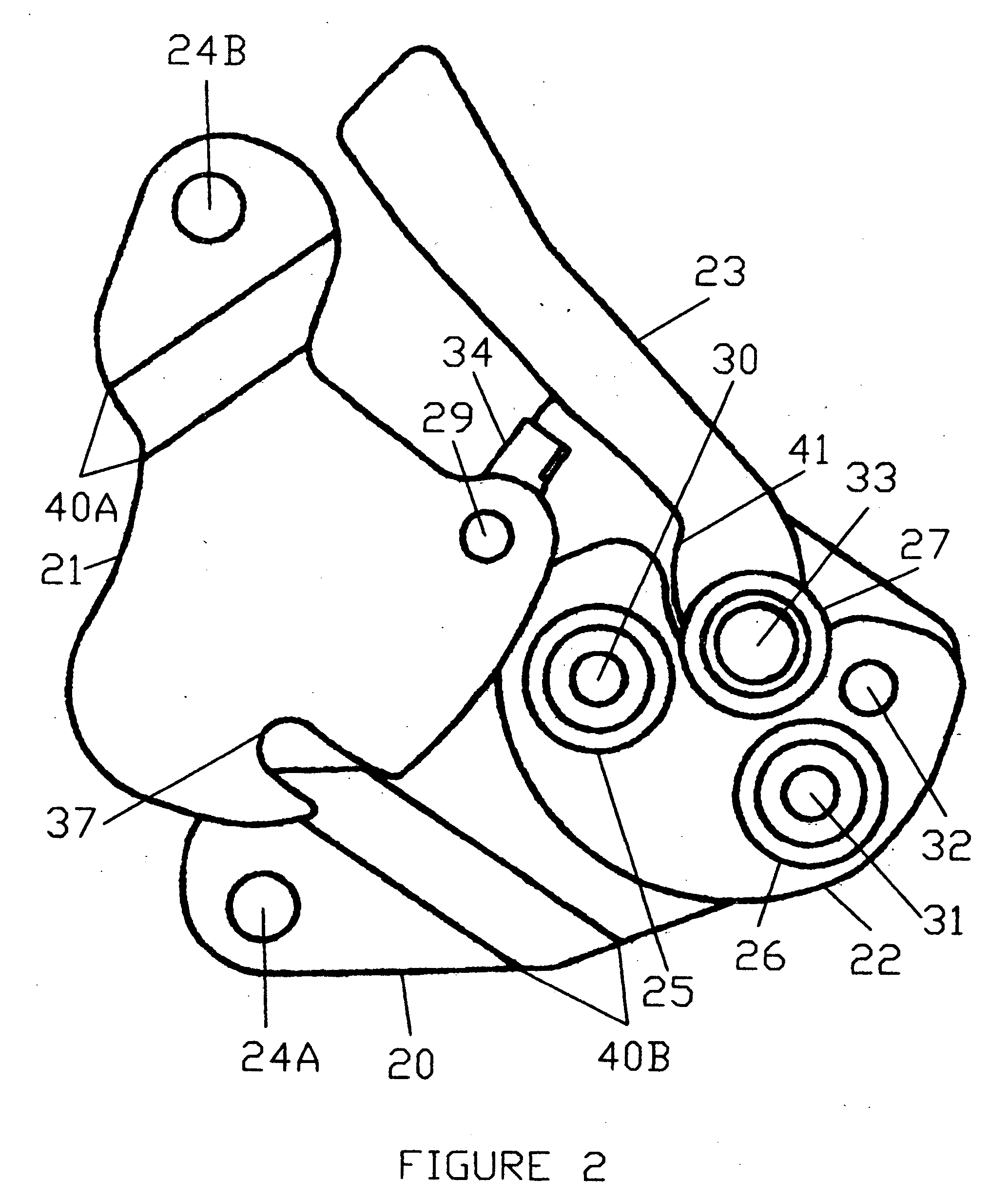
[0019]In FIG. 2, the door plate 21 is connected to the base plate 20 about a stud 29 that it rotates about to access the interior for inserting or removing the rope 39.

[0020]FIG. 4 shows the spring retainer 36 upon which the door rests. The door plate 21 has a connection point 24B that aligns with the connection point 24A on the base plate 20 when in use to secure the door plate 21 closed.

[0021]FIG. 2 shows a slot 37 in the door plate 21 that fits under the head of the stationary pulley stud 33 to aid in preventing the door plate 21 from being forced open by the rope 39. The slot 37 in the door plate 21 is opposite the door connection point 24B....


PUM


Abstract

A descender comprises a base plate (20) having a point of connection (24A) to a harness and a pivoting plate (22) mounted pivotally on the base plate (20) about an axis with the pivoting plate (22) having two spaced rotating pulleys (25 and 26) for engaging a rope (39). The base plate (20) has a rotating stationary pulley (27) mounted thereon to provide opposition to rotating pulleys (25 and 26) which are mounted on the pivoting plate (22). A control handle (23) with a cam surface (41) presses against the pivoting plate (22) which increases the space between rotating pulleys (25 and 26) on the pivoting plate (22) and the stationary pulley (27) that is secured to the base plate (20), thereby relieving the clamping effect. A speed regulator (34) stops the control handle (23) from full travel, allowing less than maximum rate of descent. A door plate (21) protects the internal parts when secured closed.

Description

FIELD OF INVENTION[0001]This invention relates to self-locking descenders.BACKGROUNDPrior Art[0002]Abseiling is a method of travel used for descent along a rope on steep surfaces such as cliffs or tall buildings. The reason for this activity varies from recreational purposes to rescue of persons to inspection of tall structures such as buildings, towers, or bridges.[0003]Abseiling is accomplished by using a descender which creates a tortuous path for the support rope which is affixed to a support base at the upper end and routed through the descender. The other end of the rope is allowed to hang free as a loose end. The operator controls the rate of descent by utilizing a device included on the descender or by holding tension on the loose end of the rope.[0004]The descender has evolved over time from very simple friction-causing devices through which the rope is wound to more complex devices which include single-lock devices such as U.S. Pat. No. 5,076,400 and double-lock devices su...

Claims


Application Information

Patent Timeline
IPC IPC(8): A62B1/14
CPCA62B1/14
Inventor ARMS, JOHNNY WAYNE
Owner ARMS JOHNNY WAYNE
Why Eureka
Try Eureka