
Method for manufacturing nozzle plate

Active Publication Date: 2009-05-14
BROTHER KOGYO KK
View PDF3 Cites 1 Cited by
  • Summary
  • Abstract
  • Description
  • Claims
  • Application Information

AI Technical Summary

Benefits of technology

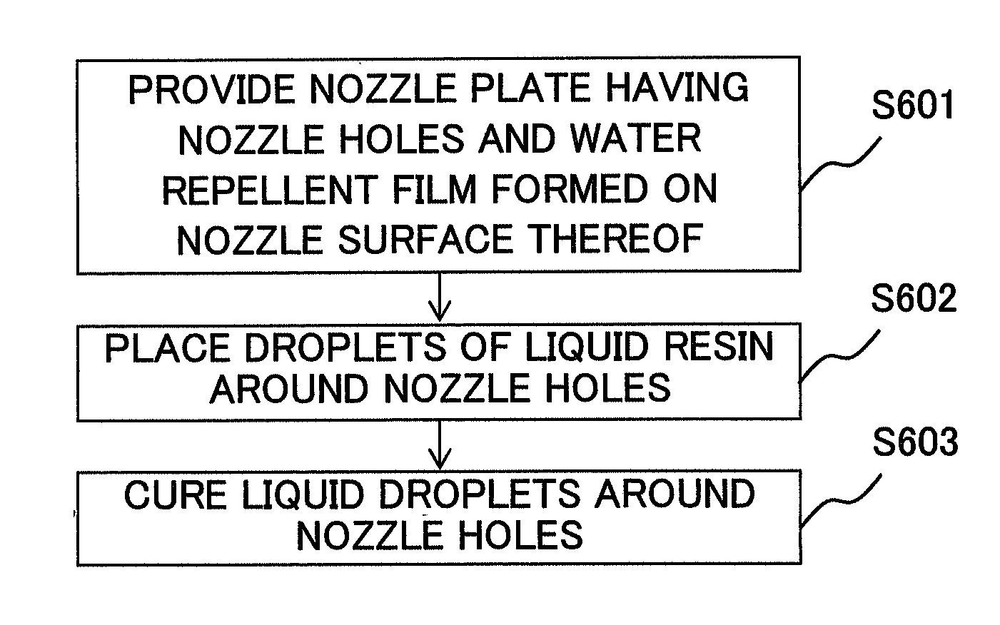
[0010]The present invention provides a method for manufacturing nozzle plate in which, projections for avoiding a contact with the recording medium can be formed easily around the nozzle holes.

Problems solved by technology

Since the nozzle surface faces the recording medium, sometimes, the recording paper makes a contact with the nozzle surface due to a jamming of the recording paper, and the nozzle surface or the water repellent film formed on the nozzle surface is damaged.
When the nozzle surface or the water repellent film near the nozzle holes is damaged, a jetting direction of the ink is inclined, and ink droplets are not formed as predetermined, thereby making it impossible to carry out normal jetting.
Besides, since such projections are not provided at a downstream side of the transporting direction of the recording paper, of each ink jetting hole, there is a possibility that the recording paper makes a contact with the nozzle surface due to jamming of the paper, and the water repellent film is damaged.

Method used


Image

  • Method for manufacturing nozzle plate
  • Method for manufacturing nozzle plate
  • Method for manufacturing nozzle plate

Examples


Embodiment Construction

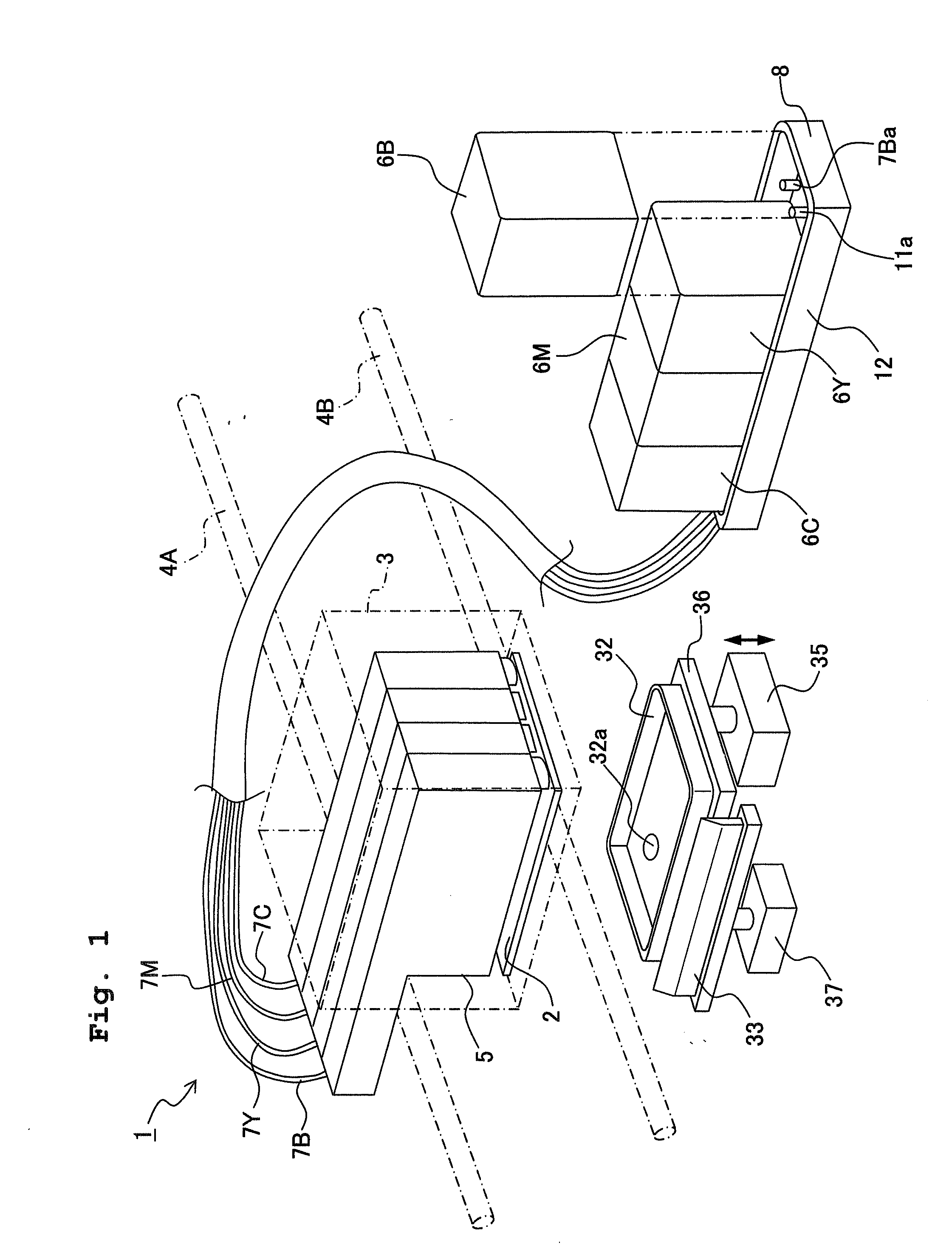
[0029]An embodiment of the present invention will be described below by referring to the accompanying diagrams. In the following description, suffixes B, Y, M, and C assigned to each reference numeral are for inks of black, yellow, magenta, and cyan color respectively.

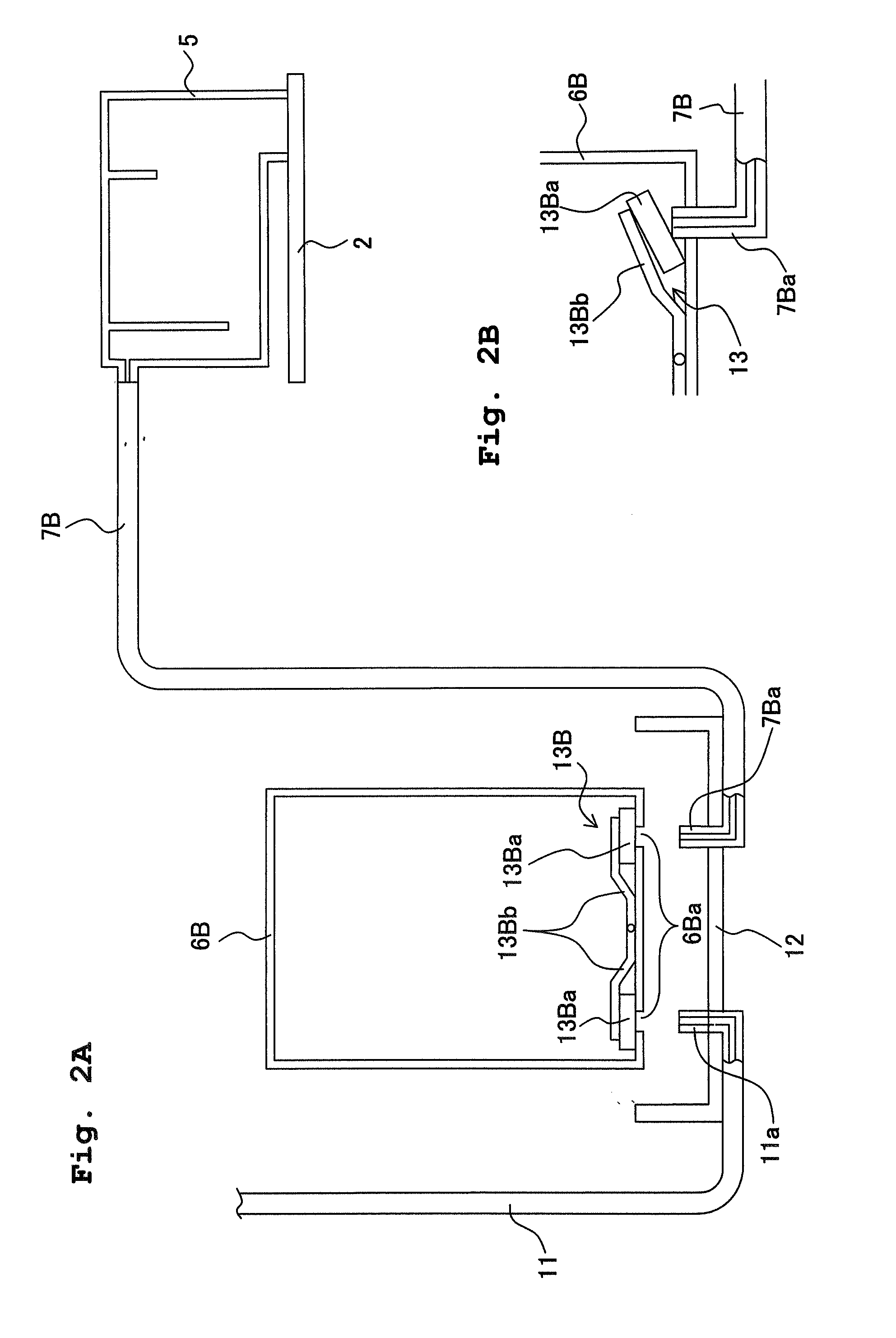
[0030]FIG. 1 is a perspective view showing an overall structure of an ink-jet recording apparatus according to the present invention, FIG. 2A is a diagram showing a positional relationship between an ink tank and an ink cartridge, and FIG. 2B is a diagram showing a connecting state of the ink cartridge and an ink supply tube.

[0031]As shown in FIG. 1 and FIG. 2A, an ink-jet recording apparatus 1 includes an ink-jet head 2. The ink-jet head 2 is held by a head holder 3 which relatively moves with respect to a recording paper (not shown in the diagram) as a recording medium. The ink-jet head 2 has nozzle groups which jet inks of plurality of types. The head holder 3 reciprocates along guide rails 4A and 4B extending in a ...


PUM


Abstract

A method for manufacturing a nozzle plate includes providing a substrate having a nozzle surface in which a plurality of nozzle holes jetting a liquid is formed, and on which a water repellent film is formed, placing a plurality of droplets of a liquid resin around each of the nozzle holes, and curing the liquid droplets to form projections of a constant height around the nozzle holes. By placing the plurality of droplets of the liquid resin to surrounding area of each of the nozzle holes, and curing the droplets, it is possible to form the projections which prevent a recording medium from making contact with the nozzle surface.

Description

CROSS REFERENCE TO RELATED APPLICATION[0001]The present application claims priority from Japanese Patent Application No. 2007-295065, filed on Nov. 14, 2007, the disclosure of which is incorporated herein by reference in its entirety.BACKGROUND OF THE INVENTION[0002]1. Field of the Invention[0003]The present invention relates to a method for manufacturing a nozzle plate.[0004]2. Description of the Related Art[0005]An ink-jet recording apparatus which records on a recording medium by jetting an ink from nozzle holes of an ink-jet head has hitherto been known. A common example of such ink-jet head includes a nozzle plate, in which a plurality of nozzle holes for jetting an ink is formed, on a lower side, and a water repellent film, which avoids adhering of the ink to a nozzle surface, is formed on a nozzle surface which is the lower surface of the nozzle plate.[0006]Since the nozzle surface faces the recording medium, sometimes, the recording paper makes a contact with the nozzle surf...

Claims


Application Information

Patent Timeline
IPC IPC(8): B41J2/16
CPCB41J2/055B41J2/14209B41J2/1433B41J2/1606B41J2002/14419B41J2/1626B41J2002/14217B41J2002/14225B41J2002/14306B41J2/162
Inventor ITO, MASAHARU
Owner BROTHER KOGYO KK
Learn More