Video Projection System

a projection system and video technology, applied in the field of video projection systems, can solve the problems of projector equipment being unexpectedly turned over by users, documents failing to take into account the protection projector equipment scratches or the position of the projector mirror deviating from the adjusted set position, etc., to reduce the possibility of occurrence of erroneous failure and the effect of turning over the projector equipmen

Inactive Publication Date: 2009-05-14
MAXELL HLDG LTD
View PDF5 Cites 16 Cited by
  • Summary
  • Abstract
  • Description
  • Claims
  • Application Information

AI Technical Summary

Benefits of technology

[0012]The present invention is devised in view of the above-mentioned problems, and accordingly, an object of the present invention is to provide a projector apparatus incorporating a protection mechanism for preventing a projection mirror from being exerted with any external force.
[0013]To the end, according to the present invention, there is provided a projector apparatus attached thereto with a roll bar for protecting the projection mirror from damage or breakage in order to decreasing an external force which is exerted to a projection mirror upon a turnover.
[0018]According to the present invention, the exertion of an external force exerted to the projection mirror, caused by a turnover of the projector apparatus, can be reduced, thereby it is possible to reduce the possibility of occurrence of erroneous failure such as breakage or damage.

Problems solved by technology

Thus, for example, there would be possibly caused such a risk that the reflection surface of the projection mirror scratches or the position of the projection mirror is deviated from its adjusted set position, being caused by a turnover of the projector apparatus (as will be detailed later in this embodiment).
Further, should the position of the projection mirror be deviated from its adjusted set position, there would be caused a problem such as a positional deviation of a projected image or a defocus of the image.
However, the above-mentioned Patent documents fail to take into sufficient consideration with the protection of the projection mirror against any breakage or damage thereof.
Among these set-up arrangements, in particular, the downward projection arrangement (the vertical arrangement or the desk-top arrangement) for inclining the direction of image projection downward, would possibly cause the projector apparatus to be unexpectedly turned over by the user since the gravitational center of the apparatus becomes unstable (will be detailed later in this embodiment).
Further, there would possibly be caused such a failure that the projector apparatus is accidentally turned over when the projector apparatus is displaced.
That is, in the conventional technology, there would be possibly caused such a problem that the projection mirror is broken or damaged due to a turnover of the projection apparatus due to erroneous handling of thereof by the user.

Method used


Image

  • Video Projection System
  • Video Projection System
  • Video Projection System

Examples


Embodiment Construction

[0028]Explanation will be hereinbelow made of a best mode for implementing the present invention with reference to the accompanying drawings. It is noted that like reference numerals are used to denote like parts throughout the drawings. Further, no duplicate explanation will be made to those which will have been once explained in order to avoid complexity in explanation. Further, in the following explanation, a liquid crystal panel is used as the image display element. However, the present invention should not be limited thereto.

[0029]The present invention is characterized by the provision of a roll bar for preventing a projection mirror which is set up on the outer wall surface of a housing, from being damaged or broken when a projector apparatus is turned over.

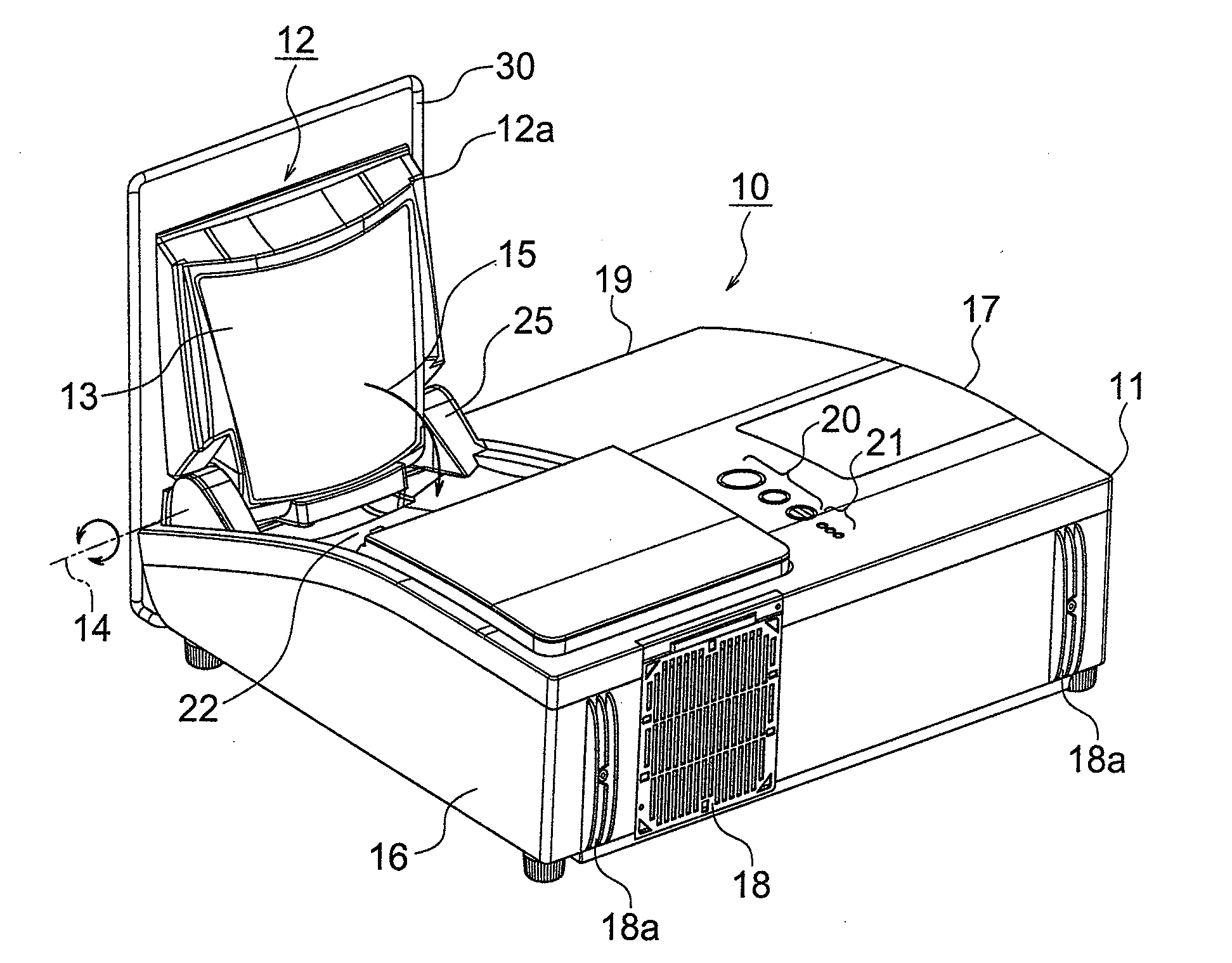
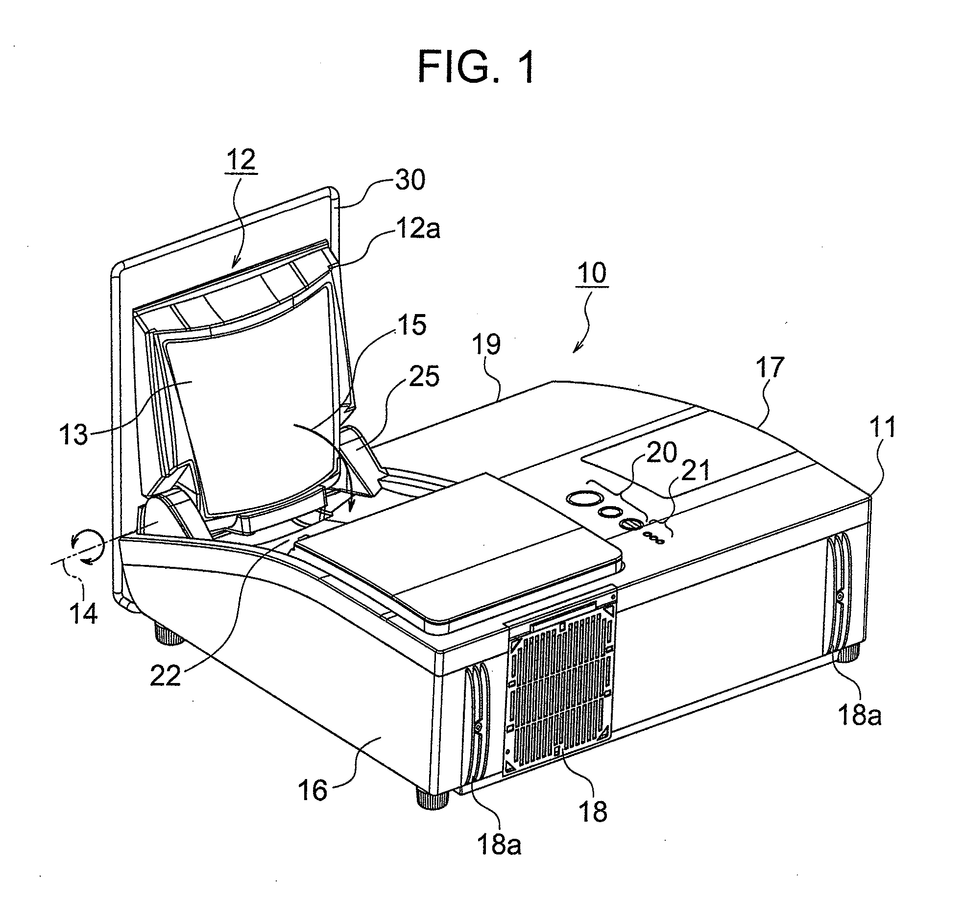
[0030]FIG. 1 is an exterior view illustrating a projector apparatus in this embodiment, having a projection mirror which has been pulled up and fixed at its operating position.

[0031]As shown in FIG. 1, the projector apparat...


PUM


Abstract

A roll bar for protecting a projection mirror is attached so as to avoid exerting an external force to the projection mirror portion, direct thereto upon a turnover the projection apparatus. Further, in the case of no attachment of the roll bar for protecting the projection mirror portion, the projector apparatus is prevented from being started. Further, when the projector apparatus is carried away, the roller bar for protecting the projection mirror serves as a handle.

Description

INCORPORATION BY REFERENCE[0001]The present application claims priority from Japanese application JP2007-295038 filed on Nov. 14, 2007, the content of which is hereby incorporated by reference into this application.BACKGROUND OF THE INVENTION[0002]1. Field of the Invention[0003]The present invention relates to a technology for providing a projector apparatus.[0004]2. Description of Related Art[0005]The projector apparatus is adapted to modulate a light beam from a light source by means of a image display element such as a liquid crystal panel in response to an image signal so as to produce an optical image (the so-called picture image), and then to project the optical image onto a projection surface such as an outside screen or a wall surface by means of a projection lens or a projection mirror. These years, there have been prosperously used, as the projector apparatus, projectors in which the distance to the projection surface (projection display distance) can be extremely shortene...

Claims


Application Information

Patent Timeline
Patent Type & Authority Applications(United States)
IPC IPC(8): G03B21/28G03B21/20
CPCH04N9/3141G03B21/30
Inventor SAITO, TAKESHI
Owner MAXELL HLDG LTD
Why Eureka
Try Eureka