Method and Apparatus for Creating High Efficiency Radial Circular Lighting Distributions From a Hemispherical Lambertian Source

a technology of hemispherical lambertian sources and distributions, applied in lighting applications, lighting and heating apparatus, instruments, etc., can solve the problems of reduced product life, led light sources are expensive, and the output color and intensity of leds can be changed, so as to achieve high efficiency, reduce lens thickness, and improve efficiency

Active Publication Date: 2009-05-14
DRAGONFISH TECH
View PDF10 Cites 5 Cited by
  • Summary
  • Abstract
  • Description
  • Claims
  • Application Information

AI Technical Summary

Benefits of technology

[0016]The light energy projecting to the side strikes an outer third surface. The outer surface is shaped such that the light energy exits the lens material and enters the output pattern. An additional feature of the outer surface is that it is broken into several individual facets having progressively smaller radii as they approach the plane of the pcb. This results in a significantly reduced lens thickness making the lens manufacturable using standard injection molding processes.
[0017]It is therefore an object of the present invention to provide an improved non-imaging optical lens apparatus for the high efficiency creation of ring shaped output patterns.
[0018]It is a further object of the present invention to provide a higher efficiency and lower cost approach to the design and manufacture of ring shaped output lamps.
[0019]It is yet a further object of the present invention to provide vehicle lights such as marine vessels navigation lighting that is both efficient and cost effective.

Problems solved by technology

The primary disadvantage of LED light sources however is their cost.
Higher LED temperature results in reduced product life and can change the output color and intensity of the LED.
In production dielectric coatings are often too expensive and are difficult to create on a curved surface.
In many cases, internal reflection results in thick cross-section lens material and long beam paths inside the material.
Thick materials are inherently difficult to mold as most materials shrink when cooling creating internal stresses and surface deformations in the final part.
Also, these thick materials often have long beam paths resulting in a need for high clarity materials to minimize beam attenuation.

Method used


Image

  • Method and Apparatus for Creating High Efficiency Radial Circular Lighting Distributions From a Hemispherical Lambertian Source
  • Method and Apparatus for Creating High Efficiency Radial Circular Lighting Distributions From a Hemispherical Lambertian Source
  • Method and Apparatus for Creating High Efficiency Radial Circular Lighting Distributions From a Hemispherical Lambertian Source

Examples


Embodiment Construction

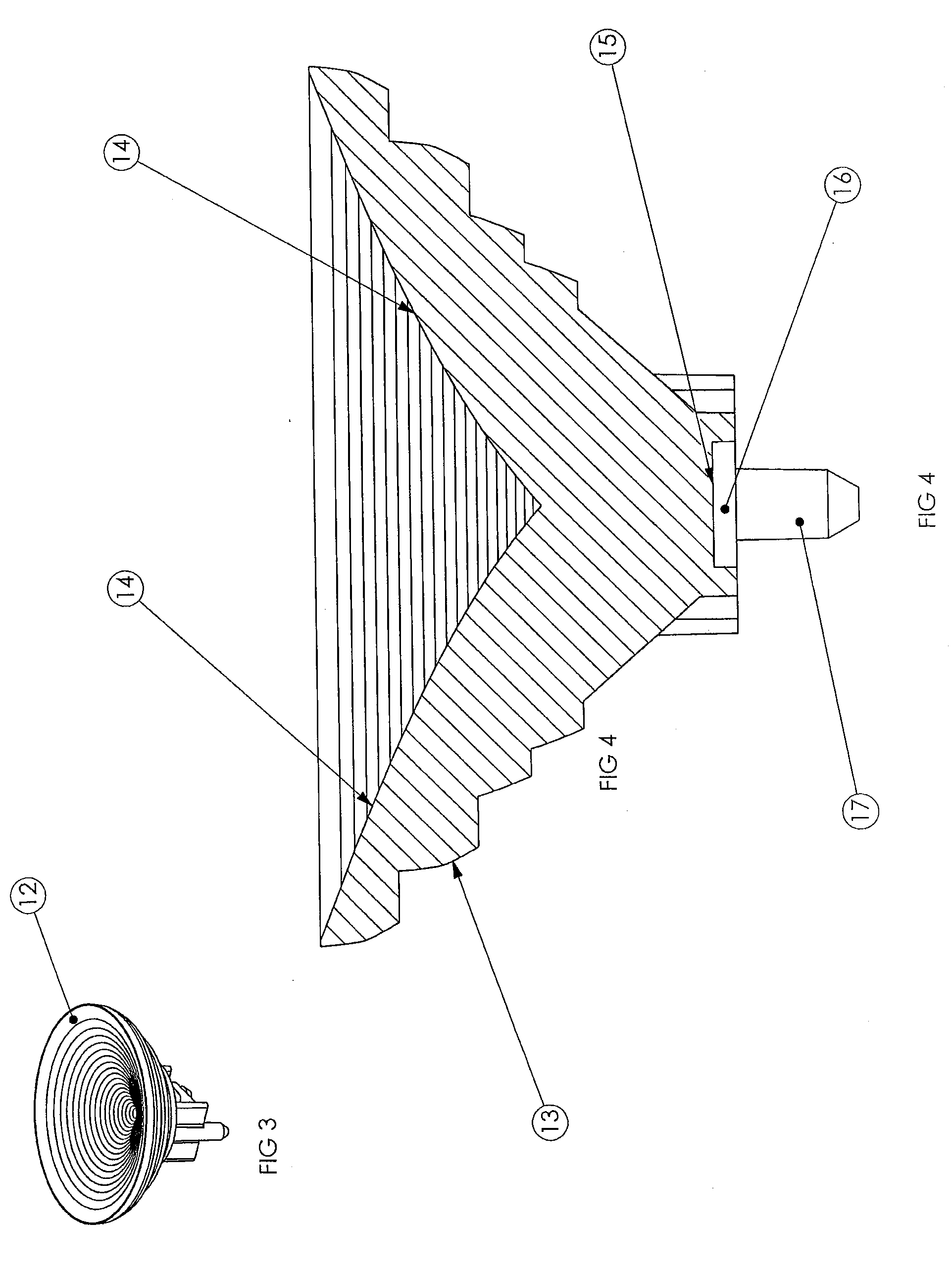
[0025]As will be described herein, the present invention relates to an improved ring shaped light pattern generating method and devices and lenses made therefrom. The lenses and devices have wide ranging uses in various applications including portable lamps and specialty lighting, homes, over-land vehicles, watercraft, aircraft and manned spacecraft electric cars, airplanes, helicopters, space stations, shuttlecraft and the like.

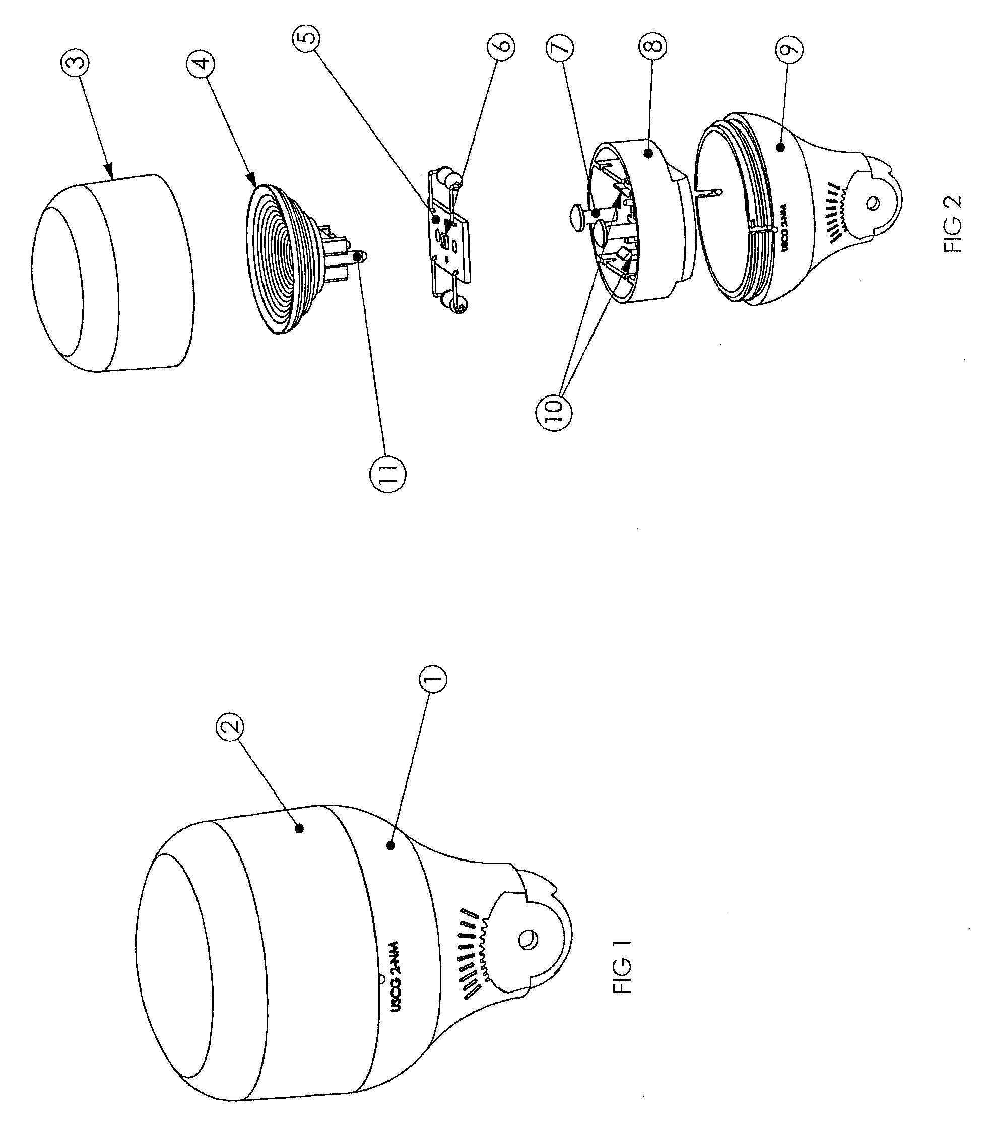
[0026]Referring now to FIG. 1, the exterior of a 360 degree output marine stem lamp which meets the coast guard requirement for a two mile navigation light. The lamp assembly includes a transparent lens cover 1 connected to an opaque black plastic base 2 and protecting the internal electronic components of the lamp.

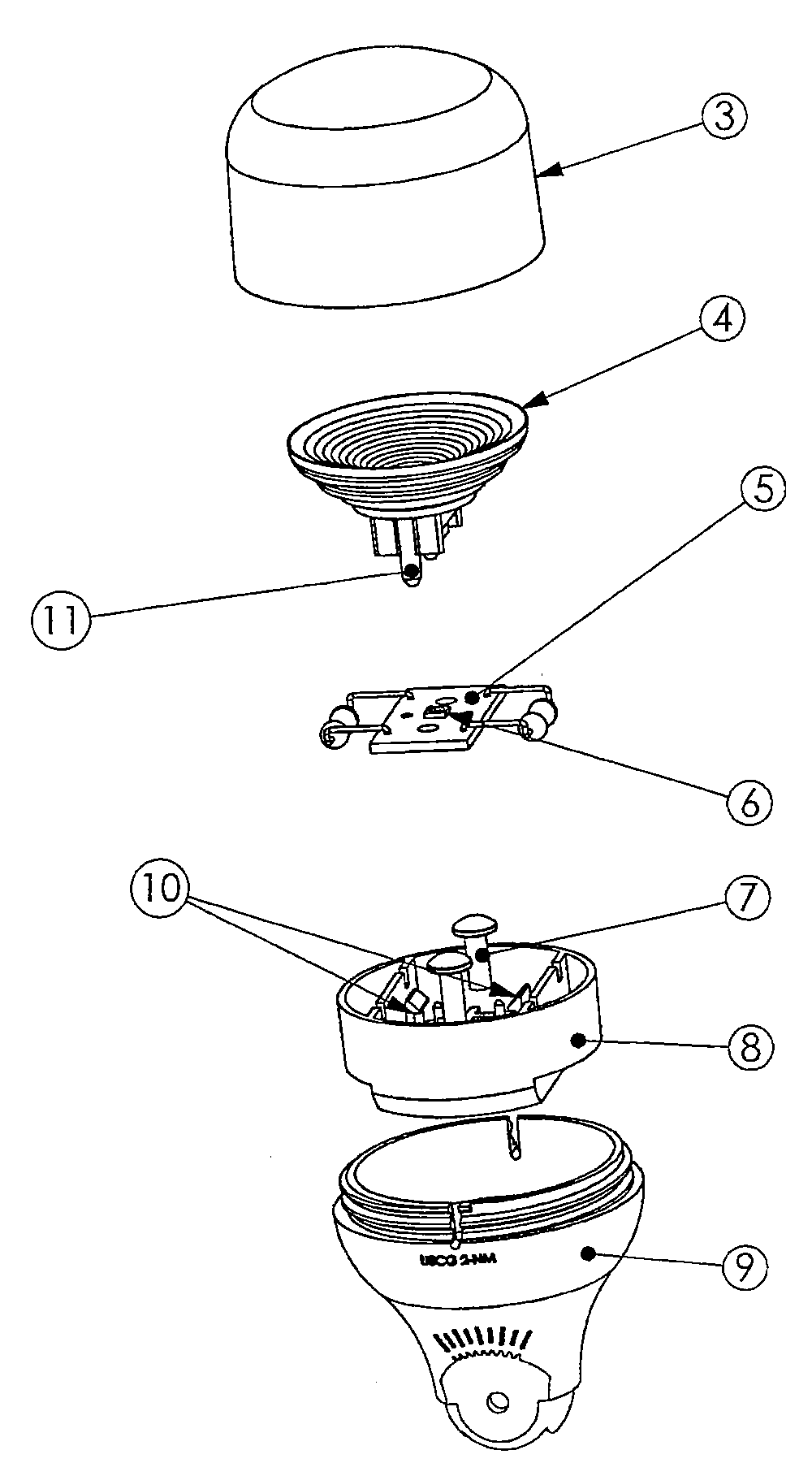
[0027]FIG. 2 is an exploded view of the edge view of the assembly shown in FIG. 1 depicting the preferred assembly required to make a stern lamp in accordance with the present invention. Transparent lens cover 3 threads on to base 9 protecting com...


PUM


Abstract

A ring generating LED lamp includes a lens section which employs internal reflection to direct the light energy from a hemispherical emitter into a ring shaped output distribution. The ring shaped distribution projects above and below the plane of the LED source. The lens has multiple internal surfaces that direct light from the LED source to provide a ring shaped output distribution.

Description

CROSS-REFERENCE TO RELATED APPLICATION[0001]The present application claims the benefit of U.S. Ser. No. 60 / 977,516, filed Oct. 4, 2007, entitled “Method And Apparatus For Creating High Efficiency Radial Circular Lighting Distributions From A Hemispherical Lambertian Source”, the disclosure of which is incorporated herein in its entirety by reference.FIELD OF THE INVENTION[0002]The present invention relates generally to the redistribution of radiant, particularly electromagnetic energy, for regulated lighting systems. More particularly, the invention is directed to the efficient distribution of light energy from a conical wide-angle light source into a substantially even intensity radially distributed band of light.BACKGROUND OF THE INVENTION[0003]There are many situations in which electromagnetic energy is to be distributed into an evenly distributed ring shaped output requirement. In the vast majority of these situations, a high efficiency transfer of source energy is desirable. Th...

Claims


Application Information

Patent Timeline
Patent Type & Authority Applications(United States)
IPC IPC(8): F21V7/00
CPCF21V5/04F21V7/0091F21W2111/00G02B19/0061G02B3/08G02B19/0071G02B19/0028F21Y2101/02F21Y2115/10
Inventor PRUSS, MARK
Owner DRAGONFISH TECH
Why Eureka
Try Eureka